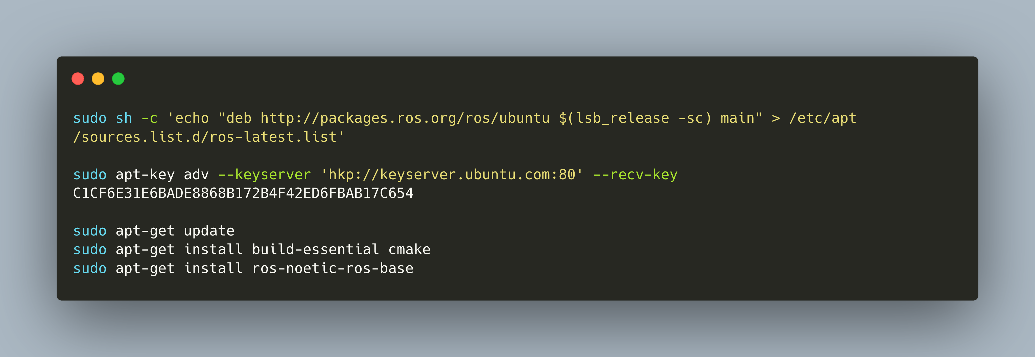
There are plenty of options for developing a mobile robot. And even plentiful are the requirements that you might want to fulfill. An overall goal in all setups should be to get the most up-to-date software running, starting from the OS to the OS packages and the application libraries.
A robot can move by processing movements commands, blindly executing them until it hits an obstacle. In contrast to this, navigation is the ability to make autonomous choices how to move to reach a goal. Fpr this, a robot needs three distinct capabilities: First, to localize itself with respect to its surroundings. Second, to build and parse a map, an abstract representation of its environment. Third, the ability to devise and execute a path plan how to reach a designated target from its current location.
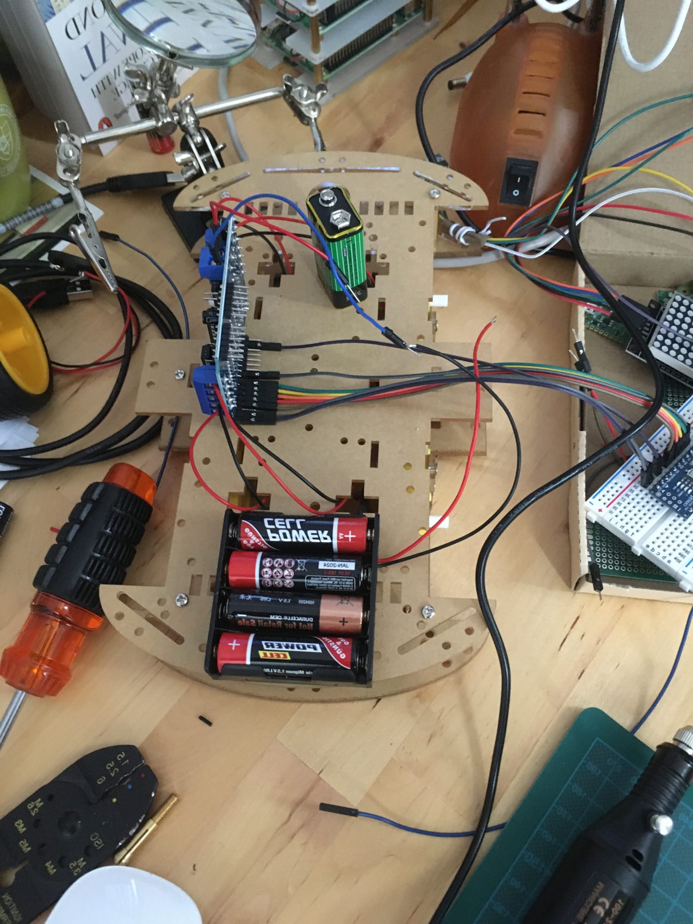
The development of my robot continues steadily. In the last post, I showed an immoveable box of the robot, which means a fully sensor equipped machine with the Raspberry Pi, the Arduino Nano, LED display and IR receiver. This box is now put on wheels so that it can move around freely.
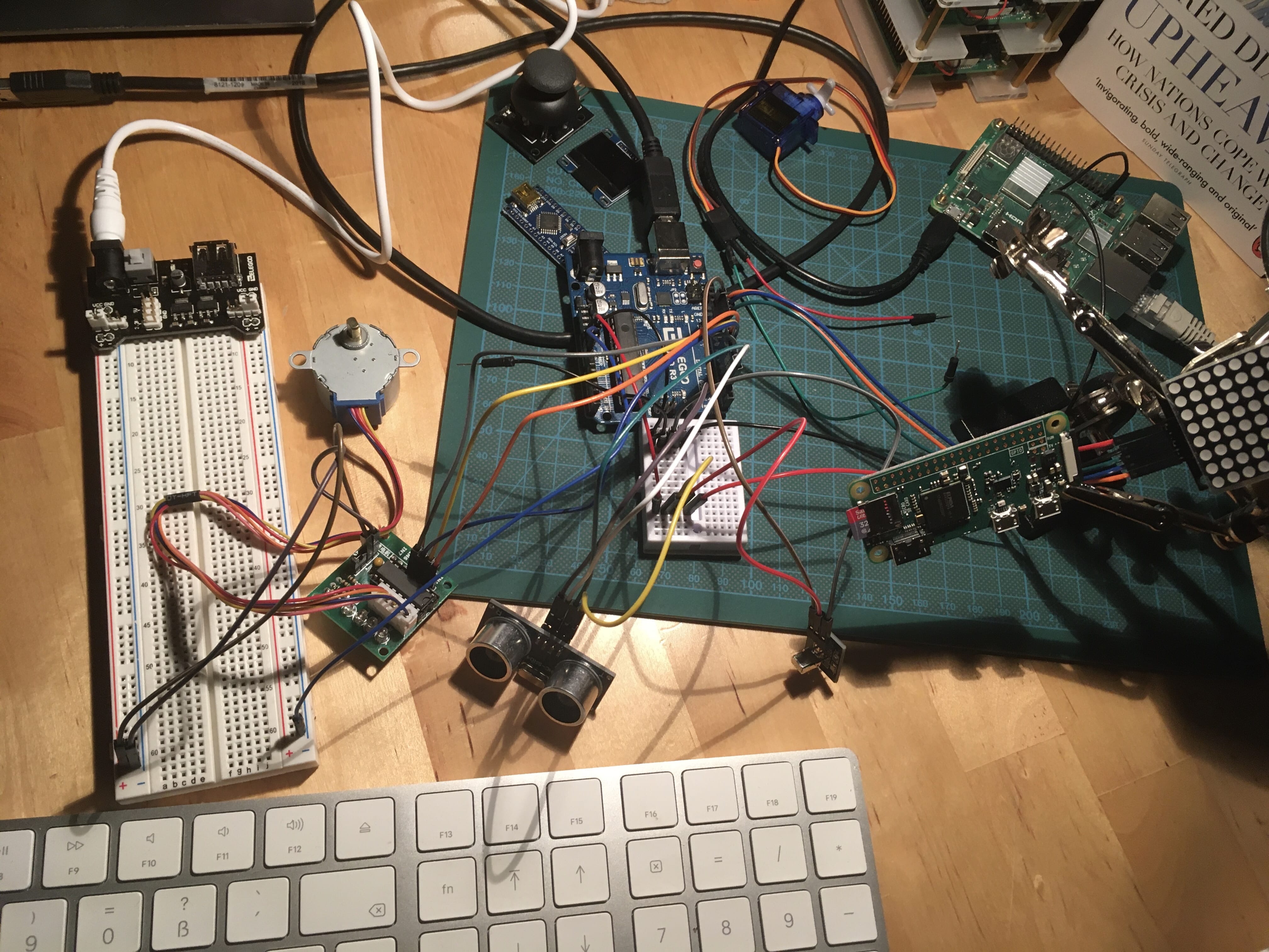
RADU is the code name for my robot project. In the last article of this series, I presented the bill of material, the type and number of items that I want to use in assembling the robots. Since this inception, I tried several sensors individually, and then gradually combined them.
To build a self-navigating robot in ROS, we need to understand the fundamentals of different aspects. The robot itself needs to be modeled in a way that transformations of its pose can be achieved. Also, the robot needs to listen and react to `Twist` data. And finally, it needs to continuously publish positional sensor data in the form of odometry messages.
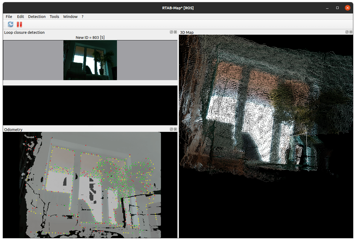
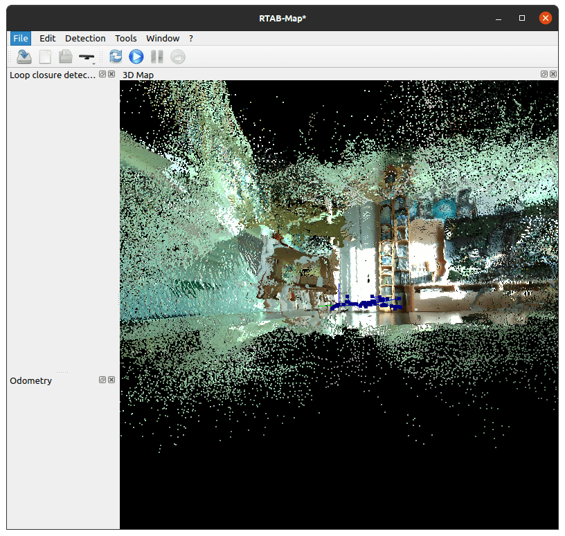
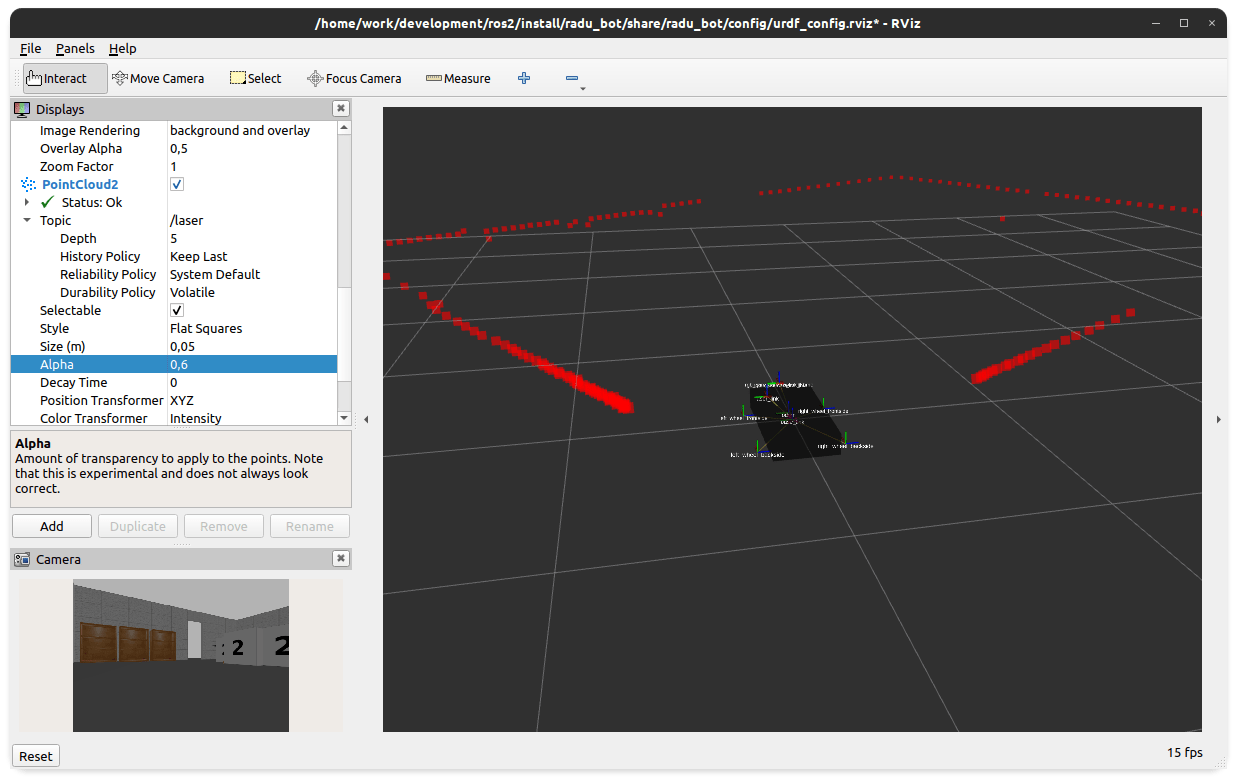
The simulation of RADU in RViz and Gazebo is progressing well. In the last articles, we learned how to launch the robot and operate it with a teleop node. In this article, we will add two visual sensors. First, an image camera to see a live feed from the robot when it moves around. Second, a depth camera sensor, which outputs a point cloud, a distance measurement of the robots' surrounding in which the colors represent how far away objects are. These two sensors help in 2D navigation and 3D object recognition.
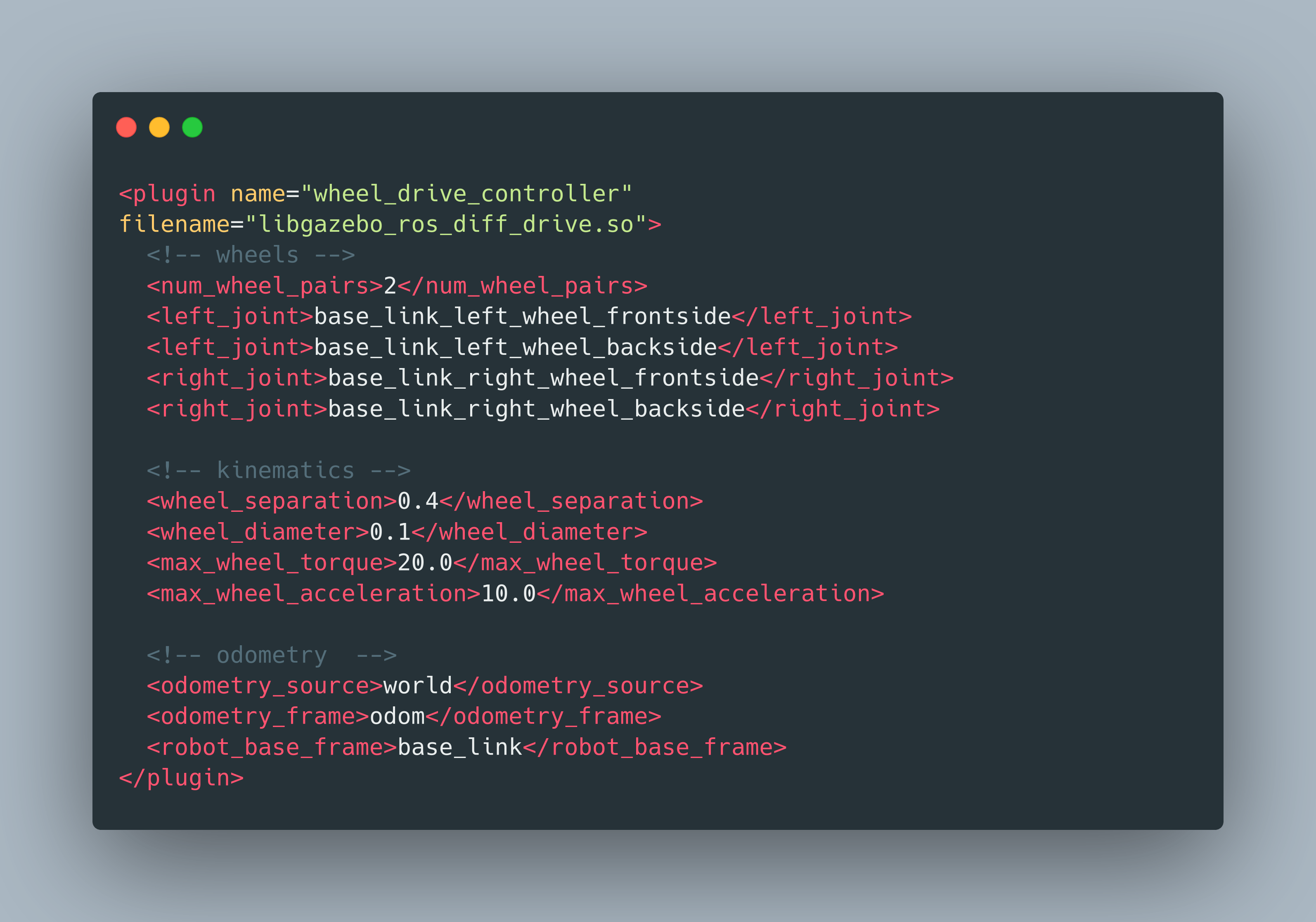
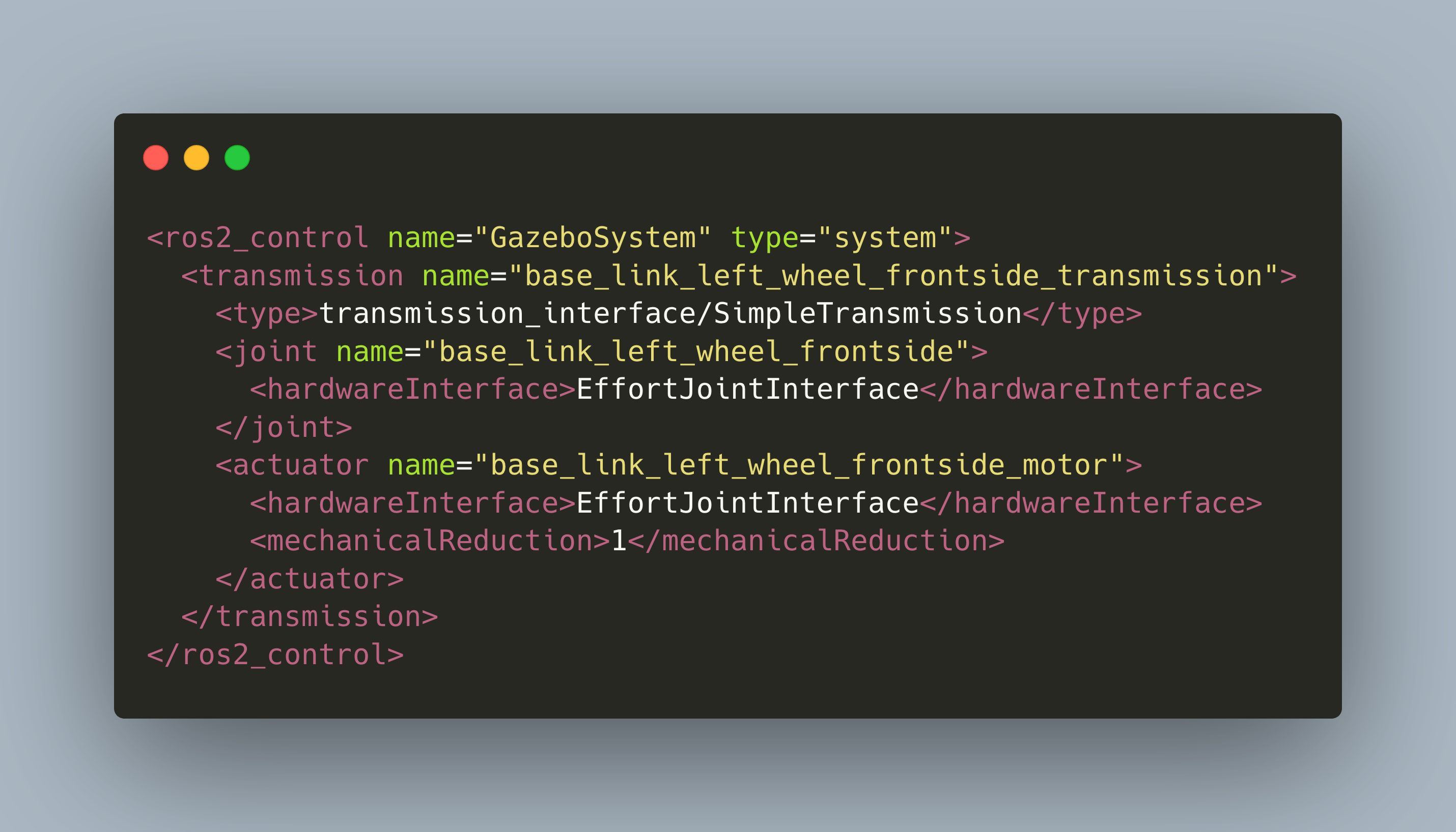
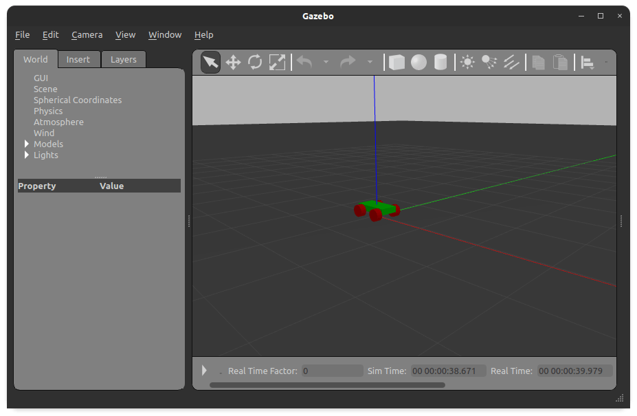
In my recent articles about ROS and my project RADU, I showed how to launch a custom robot model in Gazebo and exposing its joints via special control nodes. These nodes accept commands to change their efforts, velocity, or position. However, the nodes are not translating the commands per-se and move your robot, you still need to write the code that interfaces with Gazebo.
In the recent articles about ROS and my project RADU, I showed how to launch a custom robot model in RVIZ and in Gazebo. In RVIZ, the robot was visually rendered, and with a small build-in GUI application, we could modify the joints of the robot. The Gazebo simulation that we finished in the last post was only visual. However, the goal is to have a fully working, controllable representation of the robot that can move inside its environment.
In a robotics project, simulation is an important aspect that serves multiple purposes. First, you can test the behavioral code that you want your robot to execute. Second, you can use the simulation to test different types of hardware, for example distance sensors, cameras or 3D point cloud sensors to see which works best. Third, the same software that visualizes a simulation can be used in real time, with a real robot, to see the environment while its being scanned and navigated by the robot.
ROS2 is the ongoing effort to modernize the ROS ecosystem to a modern codebase. It includes several changes: Python-based build system, updated C/C++ language standard, new CLI commands and an updated architecture of nodes, topic and messages.