To build a self-navigating robot in ROS, we need to understand the fundamentals of different aspects. The robot itself needs to be modeled in a way that transformations of its pose can be achieved. Also, the robot needs to listen and react to Twist data. And finally, it needs to continuously publish positional sensor data in the form of odometry messages.
This article tackles each of these three areas. It explains the fundamental concepts and lists the available ROS packages to achieve the desired behavior.
ROS Navigation Essentials
According to the ROS navigation documentation page, the following assumptions and requirements need to be fulfilled by your robot:
- Its based is roughly shaped as a square
- It uses a differential drive or is holonomic wheeled
- It listens to
Twistmessage commands and translates x velocity, y velocity, and theta velocity into concrete and correct movements - It received sensor data about its external surroundings in the form of
LaserScanorPointCloud.
Considering these points, the last point is a rather drastic limitation: Other sensors such as stereo cameras, sonar and infrared cannot be used out of the box. Rather, their native data format needs to be translated to the respective topics.
To further understand the implications of these requirements, the following two sections independently discuss the required data and the components of the ROS navigation stack.
Data Requirements
Odometry Data
The transform data represents the static relationship between two coordinate references. When the robot moves, its odometry data represent the dynamic change of its velocity. In ROS, the robot needs to publish both transform data and odometry data. Abstractly speaking, the odometry data is filtered through the transform data.
Odometry data is published as Odometry and consists of these parts:
# This represents an estimate of a position and velocity in free space.
# The pose in this message should be specified in the coordinate frame given by header.frame_id.
# The twist in this message should be specified in the coordinate frame given by the child_frame_id
Header header
string child_frame_id
geometry_msgs/PoseWithCovariance pose
geometry_msgs/TwistWithCovariance twist
Source: http://docs.ros.org/en/noetic/api/nav_msgs/html/msg/Odometry.html
Sensor Data
The final type of data required for navigation are the sensor data in the form of LaserScan or PointCloud. This data is used to measure the surroundings of the robot.
Let’s investigate each one separately.
Laser Scan Data
A laser scan represents 2D data taken on a horizontal plane. The data points are taken in a specific angle, in a specific distance between individual points, and in a specific timestamp. All of this is contained in the LaserScan message type.
Header header            # timestamp in the header is the acquisition time of
                         # the first ray in the scan.
                         #
                         # in frame frame_id, angles are measured around
                         # the positive Z axis (counterclockwise, if Z is up)
                         # with zero angle being forward along the x axis

float32 angle_min        # start angle of the scan [rad]
float32 angle_max        # end angle of the scan [rad]
float32 angle_increment  # angular distance between measurements [rad]

float32 time_increment   # time between measurements [seconds] - if your scanner
                         # is moving, this will be used in interpolating position
                         # of 3d points
float32 scan_time        # time between scans [seconds]

float32 range_min        # minimum range value [m]
float32 range_max        # maximum range value [m]

float32[] ranges         # range data [m] (Note: values < range_min or > range_max should be discarded)
float32[] intensities    # intensity data [device-specific units].  If your
                         # device does not provide intensities, please leave
                         # the array empty.
Source: http://docs.ros.org/en/noetic/api/sensor_msgs/html/msg/LaserScan.html
The typical sources for laser scan is Lidar, a technology that continuously moves a laser in a planar area and detects the distance to objects.
Pointcloud Data
A pointcloud is a 3D representation of its surroundings. It consists of individual points with x,y,z data. Combining all these points give a 3D depth picture of the surroundings. Here are the contents of the pointcloud data format.
# Time of sensor data acquisition, coordinate frame ID.
Header header

# Array of 3d points. Each Point32 should be interpreted as a 3d point
# in the frame given in the header.
geometry_msgs/Point32[] points

# Each channel should have the same number of elements as points array,
# and the data in each channel should correspond 1:1 with each point.
# Channel names in common practice are listed in ChannelFloat32.msg.
ChannelFloat32[] channels
Source: http://docs.ros.org/en/noetic/api/sensor_msgs/html/msg/PointCloud.html
Pointcloud data can be obtained 3D LIDAR scans, as explained in this medium article, or from RGB-D cameras that combine special camera lenses and structured light, time-of-flight or interferometry to measure distance.
Transform Data
Data that expresses spatial relationships about the robot or the sensor needs to be translated in order to represent the actual data. On an abstract level, a mobile robot consists of different structural components, e.g. its center, its wheels, sensors mounted on top, and more. Each of these components has a base point, an absolute coordinate reference in the form of x,y,z. Now, suppose that a sensor is mounted on top of the robot. This sensor performs a laser scan of its surroundings. These measurements are made from the base point of the sensor. But to act on these, we need to transform the sensor data to match the robots center base points. For this, ROS uses a transform tree, a representation the determines the offset from the robot’s center base points to the base point of other components. For example, the translation x=1.0, y=0.0, z=5.0 means that the sensor is mounted 1.0 cm further to the front and 5.0 cam above the center base point. If you have a complete model of the robot, then these relationships are automatically computed by ROS.
This finishes the data requirements. Now, let’s consider the individual navigation stack components.
Navigation Stack Components
In the ROS navigation stack, the transform, odometry, and sensor data are utilized to determine where the robot is and, given a goal, where to move to. To achieve this, different software components of the ROS navigation stack are involved.
To start, let’s take a look at the overview provided by the official documentation. Each component will be discussed in the following.
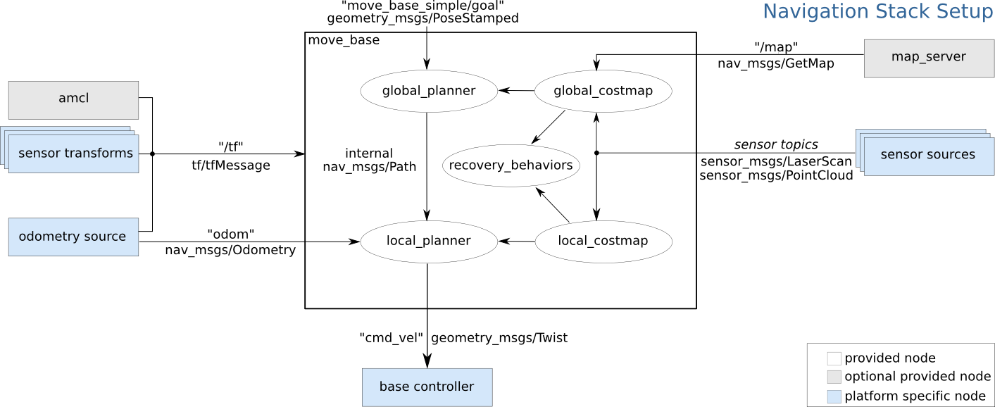
Source: https://wiki.ros.org/navigation/Tutorials/RobotSetup?action=AttachFile&do=get&target=overview_tf.png
Navigation Planner
The planner nodes are responsible to calculate all possible traversal options for a given goal. They will create cost maps for representing the effort of taking a certain path or a sequence of steps. There are two planners. The global planner is the high-level components that makes long-term planning. Its configuration options include within which distance detect obstacles will be stored in the cost map, if and how much space from the robot to an obstacle should maintain free, and the basic footprint or radius of the robot. The local planner evaluates the very next step the robot needs to take, and it needs to be configured with the robot’s basic kinetic capabilities, its min/max velocity and acceleration.
Base Controller
When the planner decides which way to go, it will send Twist messages to the cmd_vel topic. Then, a base controller of the robot needs to listen to these messages and apply the movement commands.
Map Server
The map server is an optional component with which a representation of the environment is created. A map can be recorded and saved, and then used with the next run of the robot or even exported to another robot.
Navigation Algorithms
With the data requirements explained and the pars of the navigation stack listed, we can now choose a suitable algorithm.
ROS navigation is based on SLAM, a method for providing Simultaneous Localization and Mapping. This means that the robot can make a map while moving, and use this map for localizing its position at the same time. As explained in the beginning of this article, the navigation stack requires availability of laser scan or pointcloud data. Therefore, supported navigation algorithms build on these formats.
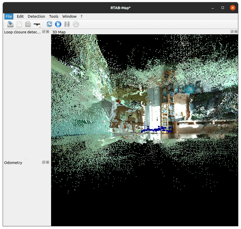
For RSO1, two SLAM algorithms exist. The library rtabmap_ros is an up-to-date RGB-D based algorithm and features a well-documented, example rich documentation. RTAB stands for Real-Time Appearance-Based Mapping and can be used to generate 3D pointcloud data and a 2D occupancy grid. A general purpose tutorial for a wide array of devices can be found in the handheld mapping tutorial. The library orb_slam2 uses simple image data from monocular, stereo and RGB-D cameras to create a map. However, it is only supported up to the ROS1 distribution melodic.
For ROS2, several options exist:
- SLAM Gmapping: ROS2 core SLAM package, requires a
sensor_msg/laser_scantopic to work. - Cartographer: Simultaneous 2D/3D Slam with a variable set of sensors
- Basalt ROS2: Basalt is a university research project that aims to combine images and IMU data for accurate localization
- Lidardslam ROS2: Using Lidar scans with OpenMP - for accurate localization
Conclusion
This article investigated the ROS navigation stack for achieving autonomous navigation for robots. First of all, we learned the basic requirements that need be fulfilled by the robot: a) its roughly square shaped, b) it uses a differential or holonomic drive, c) it provides either laser scan or pointcloud data. Second, we learned about the transform, odometry, and sensor data that needs be available. Third, we saw the different components of the navigation stack and how the process the data. In essence, navigation is based on SLAM, simultaneous localization and mapping - is the current technical standard. SLAM enables the robot to move in any environment, forming a map while moving and gaining the capabilities of navigate in this map.