In a robotics project, simulation is an important aspect that serves multiple purposes. First, you can test the behavioral code that you want your robot to execute. Second, you can use the simulation to test different types of hardware, for example distance sensors, cameras or 3D point cloud sensors to see which works best. Third, the same software that visualizes a simulation can be used in real time, with a real robot, to see the environment while its being scanned and navigated by the robot.
In my robot project, I started with ROS1 and provided a basic robot model that can be visualized with RVIZ. Then, I build a first practical prototype, entirely Arduino-based with no ROS involved. In the current phase of the project, I work on building a Gazebo compatible model with visual sensors.
This article continues the series with a jumpstart into ROS2 simulation with Gazebo. We will get to know the essential tools for creating a simulation - ROS launch files and Gazebo - and learn to apply the essential steps - choosing 3D models, placing them in the world.
The technical context for this article is Ubuntu 20.04, ROS2 Foxy, Gazebo11, but it should work with newer versions too.
Essential Robotics Simulation Terminology
This paragraph shortly lists all the terminology that is essential to understand the physical simulation aspects. Skip this section if you are firm with the vocabulary.
- Kinematics: Kinematics is a branch of physics that governs how body’s move, in the dimensions of time, location, speed and acceleration, without considering the body’s’ weight or outward forces, such as gravity
- Kinetics: Another branch of physics that considers how a body’s’ location, speed and acceleration changes when the body has a mass and is affected by forces. (In robotics, this is also called robot dynamics)
- Odometry: A method with which to estimate a bodies’ location by continuously recording movement data and compute the distance and trajectory the body has moved
- Inertia: This force is the resistance a moving body has to any other force that would change its direction, speed or acceleration
- Friction: A force that applies when two bodies in proximity to another move and resist this movement
- Joint: A joint is a mechanical element that connects two bodies. Joints have different types describing how the connected bodies move.
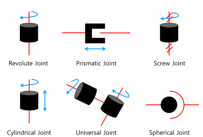
Source: ROS Robot Programming Book
- RPY Values: This acronym stands for roll, pitch, yaw that describe the movements of an object in 3D space. The object can move on these three axes according to the following graphic:
Source: wikipedia.org
Step by Step: How to Create a Simulation World
Gazebo was started outside of ROS, but became fully integrated. It focuses more on the complete physical simulation of a robot and a world. Particularly, the world provides correct physical simulation through a physics engine: The robot can bump into objects, which will move and eventually even crash on your robot. Gazebo comes with predefined world models, and you can even define your own model.
In this tutorial, we will launch a Gazebo simulation with an empty world, and then spawn a robot inside. In a nutshell, the essential steps are:
- Create a new ROS package and setup the directory structure
- Create an empty world file
- Create the launch file
- Add additional physical properties in the robots URDF model
- Parametrize the robots URDF model for running with Gazebo or RVIZ.
- Start the empty world with the launch file
Each following section details these tasks.
Step 1: Package Creation & Directory Structure
We will create a package structure that looks as follows:
radu_gazebo/
├── config
│   └── rviz.config
├── launch
│   └── launch.py
├── radu_bot
│   └── __init__.py
├── resource
├── scripts
├── test
├── urdf
│   └── core.xacro
└── worlds
│   └── room.world
├── package.xml
├── setup.cfg
├── setup.py
For convenience, just run the following commands:
ros2 pkg create  --build-type python radu_gazebo

mkdir radu_gazebo/launch radu_gazebo/world
mkdir radu_gazebo/launch radu_gazebo/world/room.world

touch radu_gazebo/launch/room.launch
Step 2: Empty World File
The room.world file is an SDF file that will contain <model> tags of everything we want to simulate: Objects like walls, windows, and furniture. We will start with a simple empty world and new objects add step-by-step.
<!-- FILE: world/room.world -->
<?xml version='1.0'?>
<sdf version="1.6">
<world name="room">
  <include>
    <uri>model://sun</uri>
  </include>
  <include>
    <uri>model://ground_plane</uri>
  </include>
</world>
</sdf>
You can load this file into Gazebo manually. But since we will ultimately also spawn a robot in this model, its best to continue with the launch file straight ahead.
Step 3: Launch File
As we learned in the last article, ROS2 does not support XML launch files anymore, and instead Python files are used.
The launch file that we use wraps the launch command from the gazebo_ros package, and provide a world argument.
#!/usr/bin/python3
import os

from ament_index_python.packages import get_package_share_directory
from launch import LaunchDescription
from launch.actions import DeclareLaunchArgument
from launch.actions import IncludeLaunchDescription
from launch.launch_description_sources import PythonLaunchDescriptionSource

package_name = 'radu_bot'
world_file = 'room.world'

def generate_launch_description():

    pkg_gazebo_ros = get_package_share_directory('gazebo_ros')
    pkg_radu_simulation = get_package_share_directory(package_name)

    # launch Gazebo by including its definition
    gazebo = IncludeLaunchDescription(
        PythonLaunchDescriptionSource(
            os.path.join(pkg_gazebo_ros, 'launch', 'gazebo.launch.py'),
        )
    )

    # load the world file
    world_arg = DeclareLaunchArgument(
          'world',
          default_value=[os.path.join(pkg_radu_simulation, 'worlds', world_file), ''],
          description='SDF world file')

    return LaunchDescription([
        gazebo,
        world_arg
    ])
Step 4: Extend the Robot Model with Gazebo Tags
In order to use our URDF model from RViz in Gazebo, we need to make several changes to the model.
First of all, we need to provide additional physical aspects to the robot so that it behaves correctly in a simulation. Second, the visual appearance of the robot differs. The color and text definition of an RVIZ model is not applicable. If you use meshes, they need to be changed as well. Third, we also need additional plugins so that the Gazebo tool works properly
Lets review these changes step-by-step.
Physical Simulation Properties
Inertia
The inertia of an object is the counterforce that it applies when its current motion is influenced by another object. In Gazebo models, the <inertial> tag is used to represent this aspect.
Here is an example:
<link name="base_link">
  <inertial>
    <origin xyz="0 0 0" rpy="0 0 0"/>
    <mass value="0.25" />
    <inertia ixx="0.000486" ixy="0.0" ixz="0.0" iyy="0.000486" iyz="0.0" izz="0.000729"/>
  </inertial>
  <visual>
    <origin rpy="0 0 0" xyz="0 0 0"/>
    <geometry>
        <cylinder radius="0.09" length="0.09"/>
    </geometry>
  </visual>
</link>
The <origin> tag positions the link with respect to its parent link, here you would change the xyz values to move the estimated mass center. With <mass> you specify this links mass in kg. Finally, the <inertial> element is a matrix of how forces on x, y, and z are affecting the link. You can read the physics article on wikipedia, or use this handy python script.
Friction
Another set of variables governs the friction of links in your robot. You express this with four values. First, <kp> and <kd> provide the static and dynamic contact stiffness. Here, we use the values 100000 and 1.0, which is the default value used in many ROS projects. Second, the values <mu1> and <mu2> are the static and dynamic friction coefficients, which you can lookup on wikipedia based on the material of the link.
<gazebo reference="base_link">
  <kp>100000.0</kp>
  <kd>1.0</kd>
  <mu1>10.0</mu1>
  <mu2>10.0</mu2>
</gazebo>
Collision
This defines the hard material boundaries of your robot - it affects how gravity and other forces are applied to your robot in the simulation. These properties are expressed with the <collision> tag inside the links. Its properties are very simply: Just copy the original links’ <geometry> and <origin> values as follows.
<link name="base_link">
  <inertial>
    <origin xyz="0 0 0" rpy="0 0 0"/>
    <mass value="0.25" />
    <inertia ixx="0.000486" ixy="0.0" ixz="0.0" iyy="0.000486" iyz="0.0" izz="0.000729"/>
  </inertial>
  <visual>
    <origin rpy="0 0 0" xyz="0 0 0"/>
    <geometry>
        <cylinder radius="0.09" length="0.09"/>
    </geometry>
  </visual>
  <collision>
    <origin rpy="0 0 0" xyz="0 0 0"/>
    <geometry>
        <cylinder radius="0.09" length="0.09"/>
    </geometry>
  </collision>
</link>
Joint Characteristics
The joints in your robot should be further modeled to express their real-world behavior.
- For all non-static, non-continuous joints, set
<upper>and<lower>values - For all continuous joints, add
<effort>and<velocity>limits
<joint name="camera_joint">
  <limit upper="0.5" lower="-0.5"/>
</joint>

<joint name="left_wheel_joint">
  <limit effort="0.1" velocity="0.005"/>
</joint>
Visual Simulation Properties
To change the visuals of your robot, you have these options:
Simple Colors
This works the same as in RViz: Inside your links <visual> tags, you can reference a <color> element.
<material name="blue">
  <color rgba="0 0 0.8 1"/>
</material>

<link name="camera">
  <visuals>
    <material name="blue">
  </visuals>
</link>
Predefined Meshes
Gazebo provides a set of build-in meshes that are listed in this source code file. Apply them be adding an <material> tags inside the <gazebo> tag as follows.
<gazebo reference="base_link">
  <material>Gazebo/Grey</material>
</gazebo>
Custom Meshes
When you use custom meshes to represent your links, simple reference them in the <geometry> tag of your link as follows:
<link name="camera">
  <mesh filename:"package://radu_bot/model/meshes/camera.dae" />
</link>
Important: It is recommended to not use custom mesh files in the <collision> tags since this will affect the simulation performance. Instead, define the values based on the available <geometry> types of boxes, cylinder and sphere.
Step 5: Parametrize the Robots URDF Model for Running with Gazebo or RViz
As you see, the required changes are fundamental. And they are not backwards compatible: All the changes required for Gazebo cannot be parsed by RVIZ.
For these reasons, complex robot projects separate the URDF aspects into different XACRO files. After some experimentation, I came up with the following hierarchy.
core- contains the core macros for rendering the links and the joints of the robotrviz- the rviz master file, it defines parameters and imports other filesrviz_viusals- defines how the robot is visualized in RVizgazebo- the gazebo core file, as before it defines parameters and imports other filesgazebo_visuals- defines how the robot is visualized in gazebogazebo_physics- additional macros that calculate the<inertial>and<collision>tags of the linksgazebo_sensor- adds sensor datagazebo_controll- adds the ros-control plugin and defines macros for rendering the<transmission>tags
Let’s see how this approach works in practice. When running Xacro to render a model, the command xacro rviz.xacro -o radu_rviz_compiled.urdf will be used. This file will…
- Import the other required files
<xacro:include filename="$(find radu_bot)/urdf2/core.xacro"/>
<xacro:include filename="$(find radu_bot)/urdf2/visuals.xacro"/>
- Define the essential parameters that control the macro execution
<xacro:property name="gazebo_build" value="false" />
<xacro:property name="rviz_build" value="true" />
- Execute the macros to create the URDF model
<xacro:box_link name="base_link" size="0.6 0.3 0.05" color="${torso_color_name}" color_rgb="${torso_color_rgb}" />

<xacro:wheel_link name="right_wheel_frontside" />
<xacro:wheel_joint name="base_link_right_wheel_frontside" parent="base_link" child="right_wheel_frontside" xyz="0.2 -0.2 -0.05" />

<xacro:wheel_link name="right_wheel_backside" />
<xacro:wheel_joint name="base_link_right_wheel_backside" parent="base_link" child="right_wheel_backside" xyz="-0.2 -0.2 -0.05" />

<xacro:wheel_link name="left_wheel_frontside" />
<xacro:wheel_joint name="base_link_left_wheel_frontside" parent="base_link" child="left_wheel_frontside" xyz="0.2 0.2 -0.05" />

<xacro:wheel_link name="left_wheel_backside" />
<xacro:wheel_joint name="base_link_left_wheel_backside" parent="base_link" child="left_wheel_backside" xyz="-0.2 0.2 -0.05" />
After working with this approach for some time, I realized that the core logic of handling the variability is inside the core.xacro file: The macros for rendering links and joints have different blocks that will be triggered by the master file. See the following definition of a <link>. In line 3, an <xacro:if> condition is evaluated to add RViz-specific visuals. And in Line 14, another condition checks and applies the gazebo physical properties to the model.
<xacro:macro name="box_link" params="name size color color_rgb" >
  <link name="${name}">
    <xacro:if value="${rviz_build}">
      <visual>
        <origin xyz="0 0 0" rpy="0 0 0"/>
        <geometry>
          <box size="${size}"/>
        </geometry>
        <material name="${color}">
          <color rgba="${color_rgb}"/>
        </material>
      </visual>
    </xacro:if>
    <xacro:if value="${gazebo_build}">
      <pose>0 0 0 0 0 0</pose>
      <xacro:box_inertia m="0.6" x="0.7" y="0.4" z="0.2"/>
      <collision name="collision_${name}">
        <origin xyz="0 0 0" rpy="0 0 0"/>
        <geometry>
          <box size="${size}"/>
        </geometry>
      </collision>
    </xacro:if>
  </link>
</xacro:macro>
Step 6: Spawning a Robot
The Gazebo node is started with a launch file, but the robot needs to be spawn into the node. Thanks to the blog article how to spawn robots in ROS2, I created the following launch file.
#!/usr/bin/python3
import os
import sys
import rclpy
from gazebo_msgs.srv import SpawnEntity
from ament_index_python.packages import get_package_share_directory

package_name = 'radu_bot'

def main(args=None):
    rclpy.init(args=args)

    node = rclpy.create_node('minimal_client')
    cli = node.create_client(SpawnEntity, '/spawn_entity')

    sdf_file_path = (os.path.join(get_package_share_directory(package_name), 'urdf', 'radu_gazebo_compiled.urdf')),
    model = open(sdf_file_path[0], 'r').read()

    print("MODEL %s" %model)

    req = SpawnEntity.Request(
        name = "radu_bot",
        xml = model,
        robot_namespace = "radu",
        reference_frame = "world",
    )

    while not cli.wait_for_service(timeout_sec=1.0):
        node.get_logger().info('service not available, waiting again...')

    future = cli.call_async(req)
    rclpy.spin_until_future_complete(node, future)

    if future.result() is not None:
        node.get_logger().info(
            'Result ' + str(future.result().success) + " " + future.result().status_message)
    else:
        node.get_logger().info('Service call failed %r' % (future.exception(),))

    node.destroy_node()
    rclpy.shutdown()


if __name__ == '__main__':
    main()
The launch file can also transform the Xacro files during startup, as shown in the diff_bot example. For example, to load the Gazebo configuration, you need to execute this:
import xacro

def generate_launch_description():

    pkg_radu_simulation = get_package_share_directory(package_name)

    robot_description_path =  os.path.join(
        pkg_radu_simulation,
        "urdf",
        "gazebo.xacro",
    )

    robot_description = {"robot_description": xacro.process_file(robot_description_path).toxml()}
Launching the Robot
First, we build the current workspace.
$> colcon build --symlink-install --cmake-clean-first --event-handlers console_direct+ --packages-up-to radu_bot
Then we launch Gazebo.
$> ros2 launch radu_bot gazebo.launch.py
[INFO] [launch]: All log files can be found below /home/devcon/.ros/log/2021-05-30-09-07-30-541933-giga-36879
[INFO] [launch]: Default logging verbosity is set to INFO
[INFO] [gzserver-1]: process started with pid [36886]
[INFO] [gzclient   -2]: process started with pid [36889]
And then spawn the robot.
$> ros2 run radu_bot spawn_radu
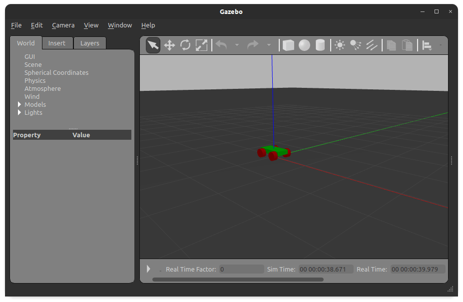
[INFO] [1622358479.722919377] [minimal_client]: Result True SpawnEntity: Successfully spawned entity [radu_bot]
Finally, the robot is rendered:

Conclusion
This article showed you how to create a Gazebo compatible simulation in ROS2 from scratch. It turned out to be lengthy process in which you need to (1) create a package, (2) create the world file, (3) create the launch file, (4) add Gazebo specific tags to our robot model, (5) parametrize your robot model to be compatible with Gazebo and RVIZ, and (6) spawn the robot entity in the simulation. Form all these steps. adding the Gazebo physics was time-intensive to learn and apply, and I hope you gained valuable insights as well. At the end, we can spawn RADU in Gazebo and RViz with a custom launch script file. And from here, we can move the robot around in its simulation.