The simulation of RADU in RViz and Gazebo is progressing well. In the last articles, we learned how to launch the robot and operate it with a teleop node. In this article, we will add two visual sensors. First, an image camera to see a live feed from the robot when it moves around. Second, a depth camera sensor, which outputs a point cloud, a distance measurement of the robots’ surrounding in which the colors represent how far away objects are. These two sensors help in 2D navigation and 3D object recognition.
Note: The technical environment is Ubuntu 20.04, ROS2 Foxy, Gazebo11, RViz2.
Visual Sensors in Gazebo
In the last article, we saw how to add a plugin to control the robot in a Gazebo simulation. Adding a visual sensor follows the same approach: Identify the plugin from the Gazebo plugin documentation, check and apply the configuration, and then add it your robots’ URDF model.
The URDF model needs to be extended as follows:
- Define the link and joint in URDF
- Optional: Define a
framelink and joint - Define a
sensorandplugintag in the<gazebo>tag
Its best practice to define any additional sensors to your robot in a separate XACRO file. This enables you to provide different configurations of your robot that are tailored for the particular simulation goal.
Adding a Camera
Let’s start with the camera plugin. As documented, different types of cameras are available. We will choose the plugin libgazebo_ros_camera.so for simulating a conventional camera.
URDF Model
The first step is to add the proper links and joints. The camera sensor is special in this regard: You need to define a link and a joint for the camera, and another link and joint for the camera frame that serves as the point of reference for the camera. Here is the required URDF part.
<?xml version="1.0"?>
<robot xmlns:xacro="http://www.ros.org/wiki/xacro" name="radu">
  <link name='rgb_cam_camera_link'>
    <visual>
      <origin xyz="0 0 0" rpy="0 0 0" />
      <geometry>
        <box size="0.02 0.04 0.01" />
      </geometry>
    </visual>
  </link>

  <joint name="rgb_cam_camera_link_joint" type="fixed">
    <origin rpy="0 0 0" xyz="0.30 0.0 0.065" />
    <parent link="base_link" />
    <child link="rgb_cam_camera_link" />
    <axis xyz="0 0 0" />
  </joint>

  <link name="rgb_cam_camera_link_frame"></link>
  <joint name="rgb_cam_camera_frame_joint" type="fixed">
    <origin xyz="0.01 0 0" rpy="0 0 0" />
    <parent link="rgb_cam_camera_link" />
    <child link="rgb_cam_camera_link_frame" />
    <axis xyz="0 0 0" />
  </joint>
</robot>
Then, we need to add the <sensor> and <plugin> tag in our robots URDF.
<?xml version="1.0"?>
<robot xmlns:xacro="http://www.ros.org/wiki/xacro" name="radu">
  <gazebo reference="rgb_cam_camera_link_frame">
    <sensor type="camera" name="rgb_camera">
      <update_rate>10.0</update_rate>
      <camera name="rgb_camera">

        <pose>0 0 0 0 0 0</pose>

        <horizontal_fov>1.3962634</horizontal_fov>
        <image>
          <width>640</width>
          <height>480</height>
          <format>YUYV</format>
        </image>
        <clip>
          <near>0.005</near>
          <far>10.0</far>
        </clip>
      </camera>

      <plugin name="camera_controller" filename="libgazebo_ros_camera.so">
        <alwaysOn>true</alwaysOn>
        <updateRate>0.0</updateRate>
        <cameraName>rgb_camera</cameraName>
        <imageTopicName>image_raw</imageTopicName>
        <cameraInfoTopicName>camera_info</cameraInfoTopicName>
        <frameName>rgb_cam_camera_link_frame</frameName>
        <hackBaseline>0.07</hackBaseline>
        <distortionK1>0.0</distortionK1>
        <distortionK2>0.0</distortionK2>
        <distortionK3>0.0</distortionK3>
        <distortionT1>0.0</distortionT1>
        <distortionT2>0.0</distortionT2>
      </plugin>
    </sensor>
  </gazebo>
</robot>
This declaration uses a helpful trick: The URDF file can contain multiple <gazebo reference="NAME"> tags, which will be parsed by Gazebo as if you would write all declarations in one global <gazebo> tag.
The main properties to configure the camera are the following items:
<image>The width, the height, and the format of the image<clip>The properties near and far regulate how the image records are clipped
And for the plugin, we need to define the update rate (0.0 means a constant stream), the topics name for the images and the camera info, and several distortion factors.
RViz Simulation
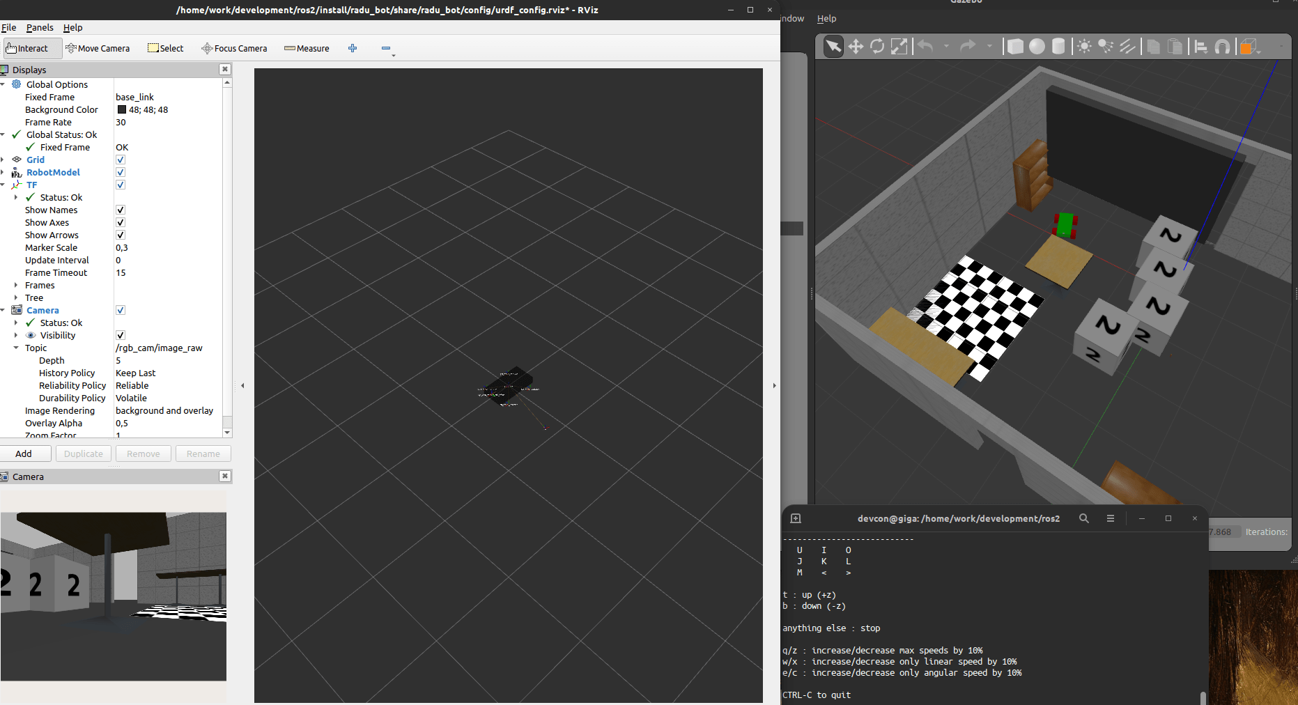
When the sensor is configured, we can just launch the robot and RViz. Inside RViz, we need to add the camera display, and then configure it to subscribe to the topic /rgb_camera/image_raw. If correctly done, you can see the image live view.
In the following screenshot, you can see the Gazebo simulation on the right side, and RViz with the camera view on the left side.
Depth Camera
With the default image camera successfully installed, we can proceed to add the depth camera.
Originally, I planned to use the Gazebo plugin for the depth sensor that I will be using in my robot: The Intel RealSense D435. During my research about this plugin, I found out that the official, specific plugin does only work with ROS1. Some users were trying to get this sensor running, as documented on this ROS answers thread - they succeed to start the controller in Gazebo, but could not get any sensor data. Therefore, I decided to use a similar, working plugin for simulating 3D point clouds: The ROS2 ray sensor.
URDF Model
As before, we first need to create the correct links in the robot model. For the depth sensor, we only need one link and one joint. Here is the relevant URDF.
<?xml version="1.0"?>
<robot xmlns:xacro="http://www.ros.org/wiki/xacro" name="radu">
  <link name='laser_link'>
    <visual>
      <origin xyz="0 0 0" rpy="0 0 0" />
      <geometry>
        <box size="0.02 0.04 0.01" />
      </geometry>
    </visual>
  </link>

  <joint name="laser_link_joint" type="fixed">
    <origin rpy="0 0 0" xyz="0.10 0.1 0.085" />
    <parent link="base_link" />
    <child link="laser_link" />
    <axis xyz="0 0 0" />
  </joint>
</robot>
Second, we add an additional <gazebo reference=""> tag that includes the <sensor> and <plugin> tags.
<?xml version="1.0"?>
<robot xmlns:xacro="http://www.ros.org/wiki/xacro" name="radu">
  <gazebo reference="laser_link">
    <sensor type="ray" name="head_laser_scanner">
      <pose>0.0 0 0 0 0 0</pose>
      <ray>
        <scan>
          <horizontal>
            <samples>181</samples>
            <resolution>1</resolution>
            <min_angle>-1.57080</min_angle>
            <max_angle>1.57080</max_angle>
          </horizontal>
        </scan>
        <range>
          <min>0.08</min>
          <max>10</max>
          <resolution>0.05</resolution>
        </range>
        <noise>
          <type>gaussian</type>
          <mean>0.0</mean>
          <stddev>0.01</stddev>
        </noise>
      </ray>

      <always_on>1</always_on>
      <update_rate>30</update_rate>
      <visualize>true</visualize>

      <plugin name="laser_scanner" filename="libgazebo_ros_ray_sensor.so">
        <ros>
          <namespace>/</namespace>
          <argument>~/out:=laser</argument>
        </ros>
        <output_type>sensor_msgs/PointCloud2</output_type>
        <frame_name>laser_link</frame_name>
      </plugin>
    </sensor>
  </gazebo>
</robot>
The sensor is of type ray and includes the following configuration options:
- The
<scan>tag can include a<horizontal>and a<vertical>tag for scanning along these definitions. Each is defined with it min and max angle, the number of samples (number of points detected), and the resolution - With
<range>you define the absolute distances in which the sensor will detect its environment - The optional
<noise>tag defines how the received measurement is cleaned up in your simulation.
Following the sensor definition, the <plugin> configures the namespace, topics, data format and the reference link for this sensor.
Gazebo and RViz Simulation
No need to modify the launch file - the new URDF file, published at the topic /robot_description, contains out new sensor and the plugin. But what will we see?
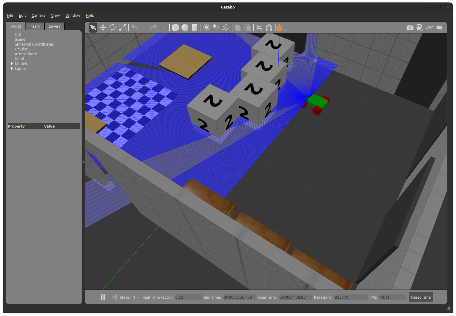
In Gazebo, we see a visual representation of the sensors: Emitted rays. I noticed that in my simulation, only the walls of the room, but not the objects, block the sensors ray - apparently, they have different physical characteristics, but that’s ok for the simulation.
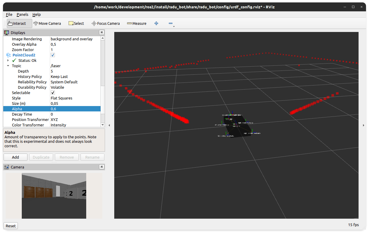
In RViz, we can see a live simulation of the sensor data, and accurately see the outline of the room when moving around. Once started, we add a new display via the Add button, selecting PointCloud2, and then configuring the topic to /laser and the size of the shown points to 0,03m. This will look as follows.

Conclusion
Enhancing a robot simulation with sensor plugins provide significant insights into the robot model. In ROS2, the official Gazebo plugins include drives, IMU, GPS, cameras and others. This article showed the essential steps for adding a sensor. First, define the links and joints for the sensor. Second, add a <gazebo> tag with the sensor and plugin configuration. Sensor show up differently in the simulation tools Gazebo and RViz. In Gazebo, the plugin exposes direct interfaces that can be controlled and/or visualized. In RViz, you need to add additional display types that will listen to the topics provided by the plugins, which will e.g. show a live-feed camera or a point cloud. Properly configured, your robot model shows its environment and gives you better control in your simulation.