A complete IOT stack running on a Raspberry Pi is an effective way to integrated different sensors for home automation. In the last articles, we learned how to manually add a temperature/humidity sensor to the home network. By using PlatformIO, we manually flash the sensor, then choose available library for interacting with a sensor, and adding additional libraries to communicate with MQTT and send correctly transformed JSON data. We have complete control over all these steps, and can configure every single character that the sensor outputs. In addition to this manual way, there are great frameworks to flash and install utility programs to sensors, and also great platforms that access several sensors and show the measurements graphically as well as giving you direct interaction with these sensors.
A complete IOT stack running on a Raspberry Pi is an effective way to integrated different sensors for home automation. In the last articles, we learned how to manually add a temperature/humidity sensor to the home network. By using PlatformIO, we manually flash the sensor, then choose available library for interacting with a sensor, and adding additional libraries to communicate with MQTT and send correctly transformed JSON data. We have complete control over all these steps, and can configure every single character that the sensor outputs. In addition to this manual way, there are great frameworks to flash and install utility programs to sensors, and also great platforms that access several sensors and show the measurements graphically as well as giving you direct interaction with these sensors.
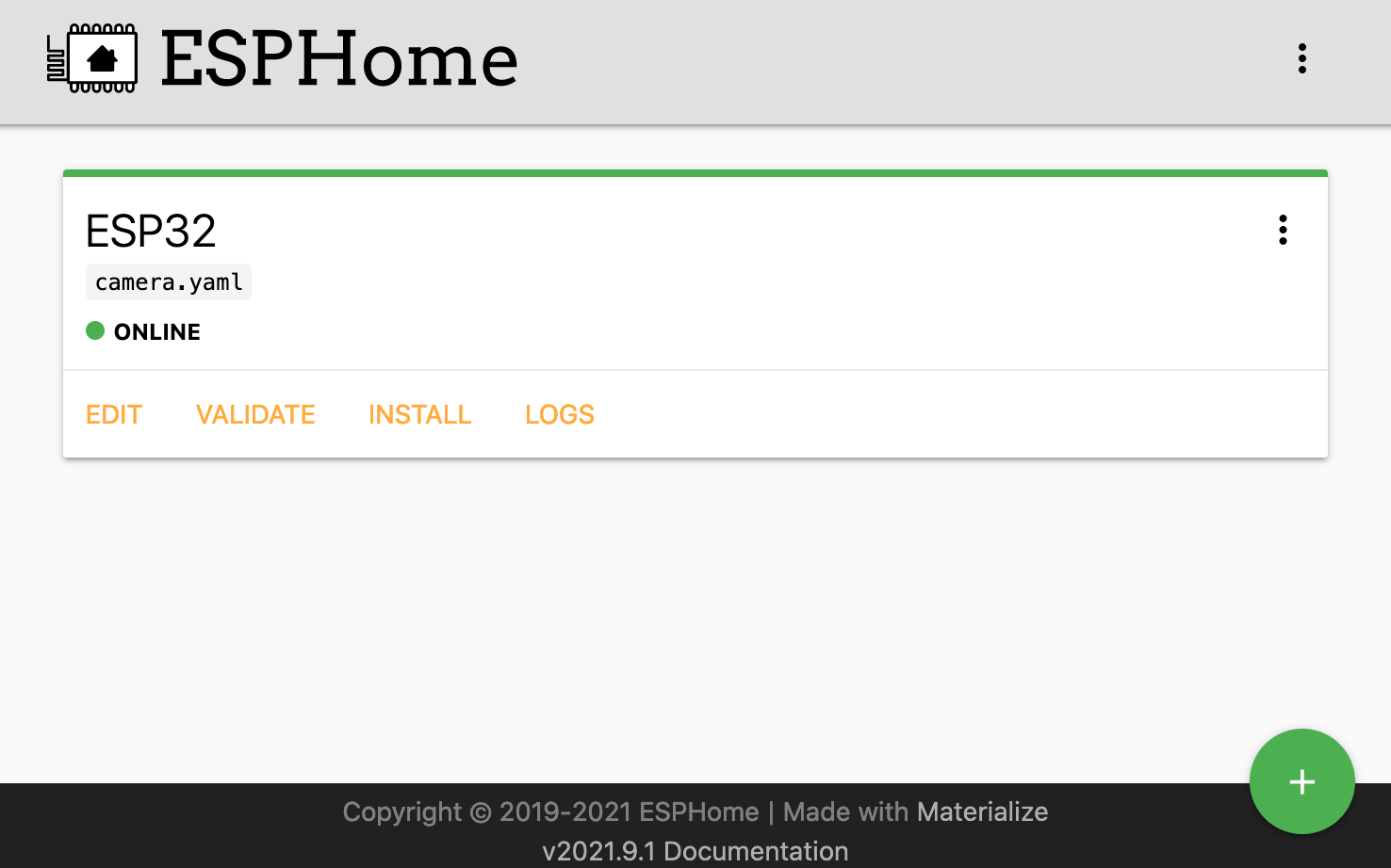
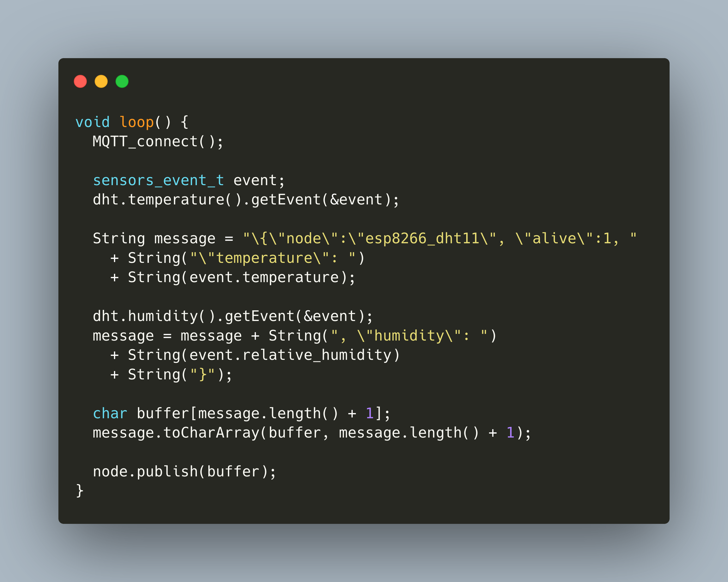
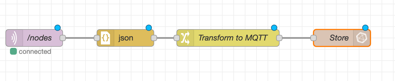
In my blog series so far, we covered how to setup the essential tools for transforming and capturing IOT data: MQTT, NodeRed, and InfluxDB. Now we will use these tools to actively collect data. The first sensor to be added is the temperature and humidity sensor DHT22. Its connected to an ESP8266 board. To flash and program it, we will use PlatformIO.
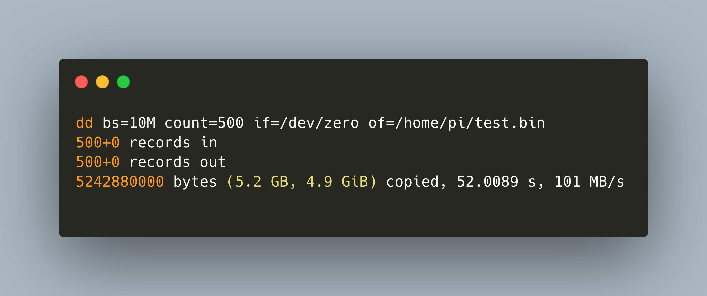
In my IOT Stack, a Raspberry Pi with an external connected disk serves as a SAMBA server. Before installing the system, I wanted to see the performance differences of various disk, their read speed, and their local and remote, via SAMBA, write speed.
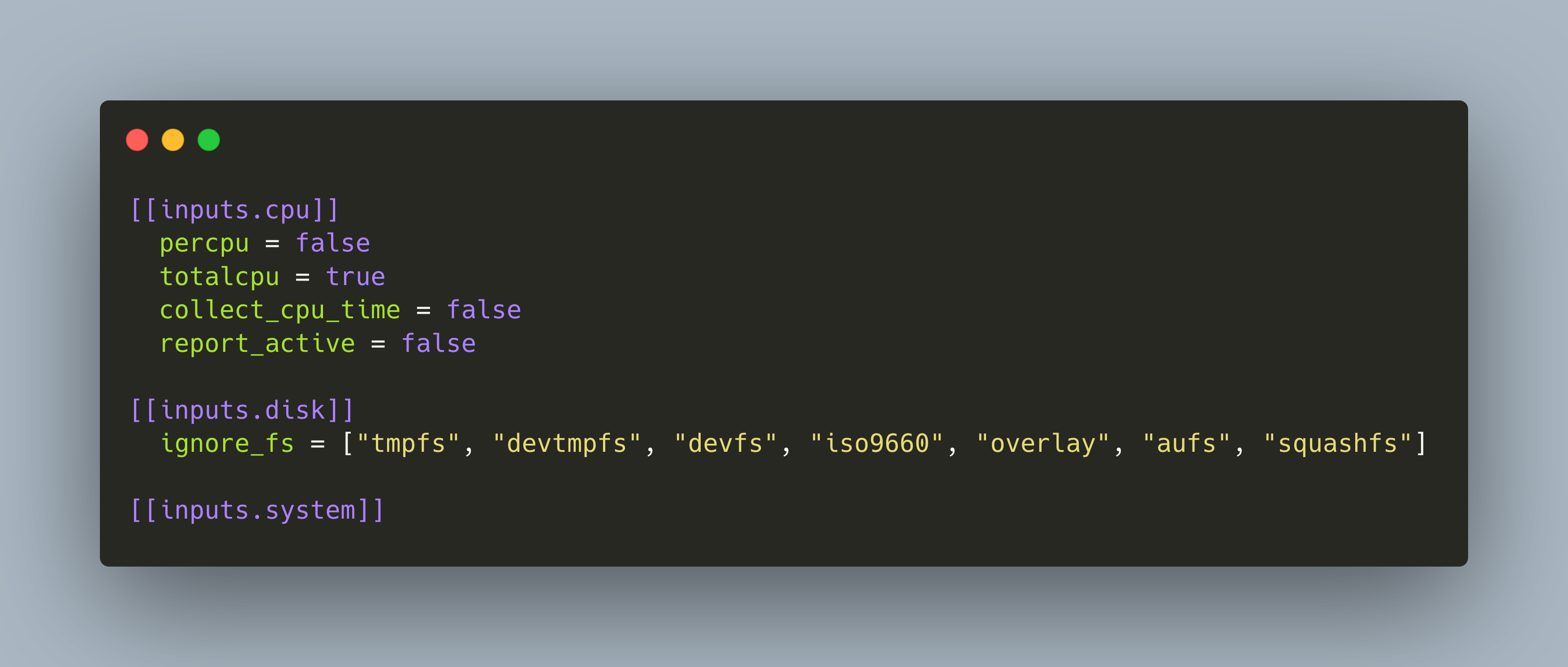
In this article, I show how to write a simple heartbeat script that runs regularly on your laptop, desktop computer or IOT device to signal that it is still operational. To store and process the data, we need an IOTstack consisting of MQTT, NodeRed and InfluxDB - see my earlier articles in the series. The device from which we measure the heartbeat needs to be able to run a Python script.
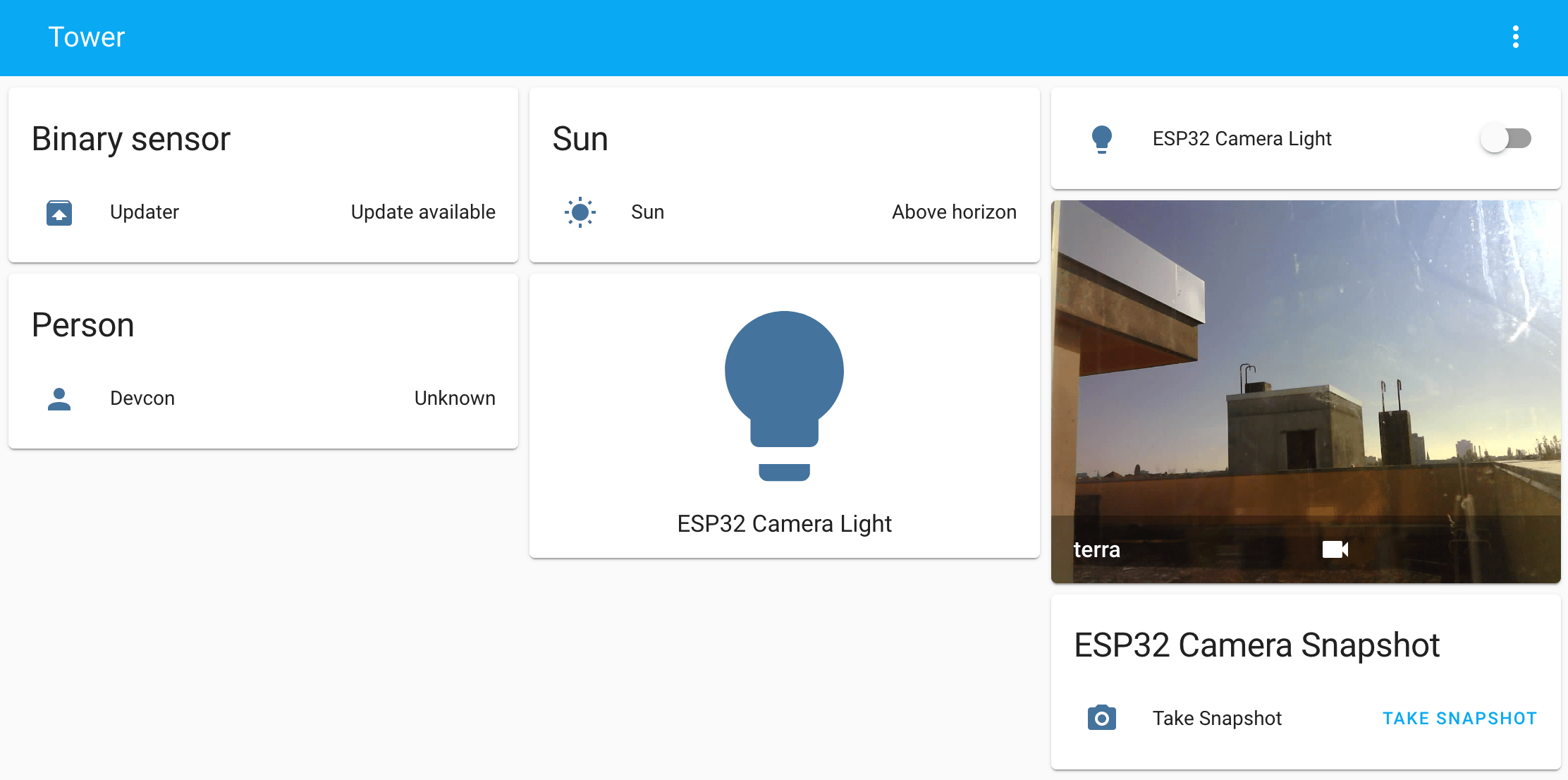
A custom IOT stack running on a Raspberry Pi is an effective way to start with adding and reading sensor data or the entry to home automation. The first article in this series showed how to install a complete stack of IOT software, namely MQTT for receiving, NodeRed for transforming, and InfluxDB for storing IOT sensor data. In addition, an optional installation of OpenMedia Vault turns the Raspberry Pi into a SAMBA/NFS share. The basics of the stack are ready, and now we can add additional sensors and software step-by-step.
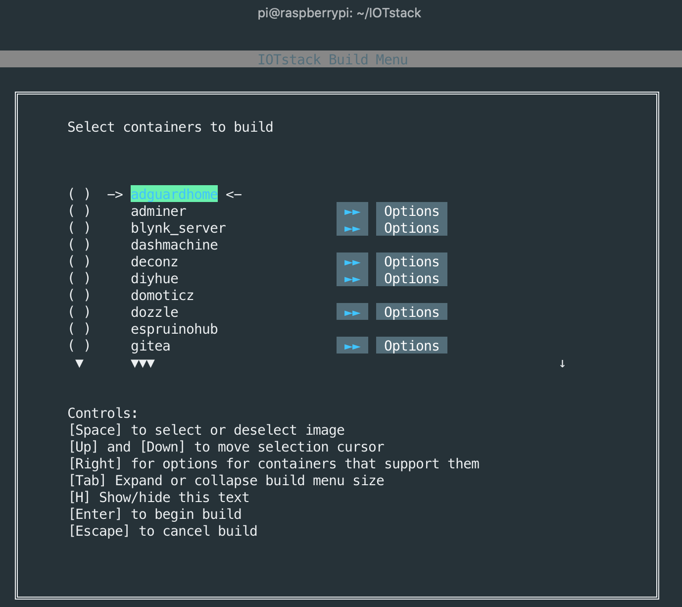
A custom IOT stack at home delivers a handy way to publish and record data from a wide variety of sensors. With additional software, you can visualize the data, access dashboards remotely, and even control some sensors. All you need is a Raspberry Pi 3B+ or 4 and a SSD Disk. For about 110€ - 150€ hardware costs and 1,5 - 2,5€ monthly power cost you can build and maintain your own IOT stack at home! This article covers everything to get you started.
It’s been more than a year working on my robot RADU. I could not get all of its goals fulfilled, and sadly, the robot is not autonomous. The journey itself was intricate, challenging, mostly fun with some rough edges. This article summarizes the project, recaps the goals and their fulfillments, and presents the hard lessons learned. It’s not easy to talk about failure, but I hope that you can take some knowledge from this description and make other decisions when working on similar projects.
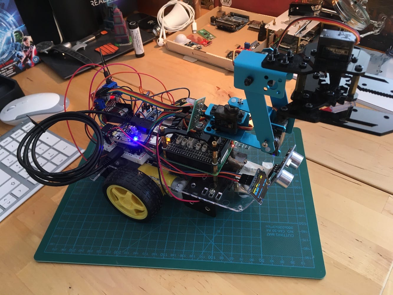
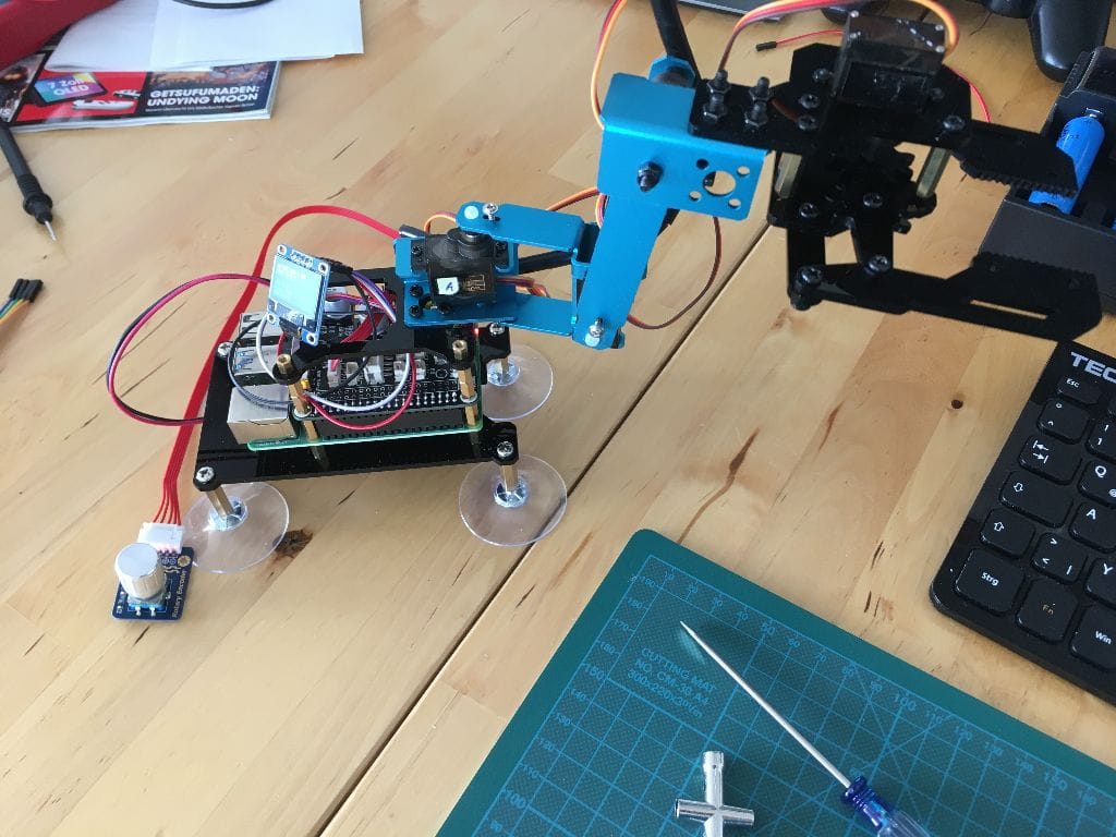
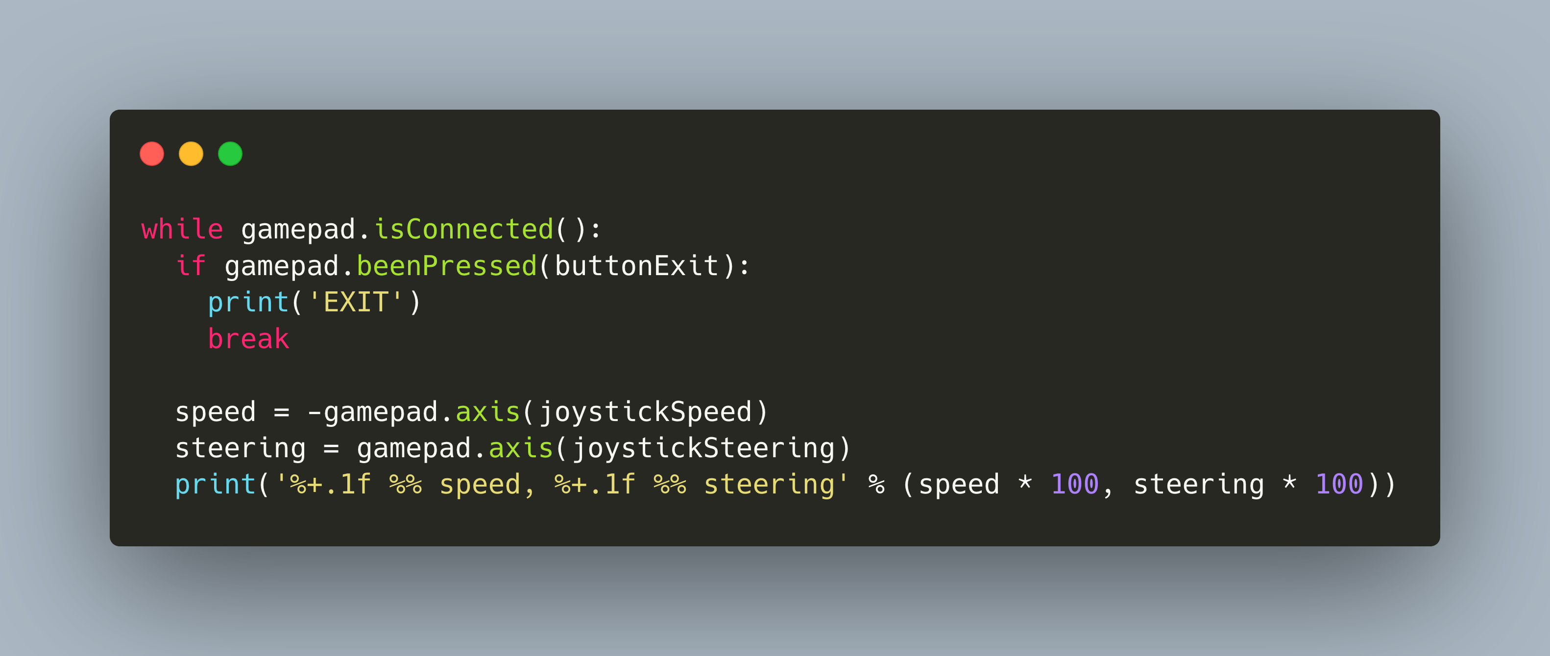
My robot RADU is a two wheeled robot that combines custom hardware for the sensor and motor, a Raspberry Pico and L293D motor shield, and a purchasable robotic arm that is controlled via a Raspberry Pi shield. For both parts of the robot, I want to use the same control mechanism and device: A game controller. To reach this goal, the last article gave an overview about the different libraries. This article is a tutorial about writing the controller software. You will learn how to use the Python library [Piborg Gamepad](https://github.com/piborg/Gamepad), and how to bridge pressed buttons or joystick to control the robots wheel movements and its arm.
After finally dropping ROS from the software stack, I continued with my robot build essentially where I left off half a year ago: A two wheeled, Raspberry Pico controlled vehicle that listens to commands via a Gamepad that are translated to movements messages. Then, I rebuild the robot, added the custom gripper module, and put everything together. It still worked. But it lacks controls. Time to investigate how to add a controller to the robot.