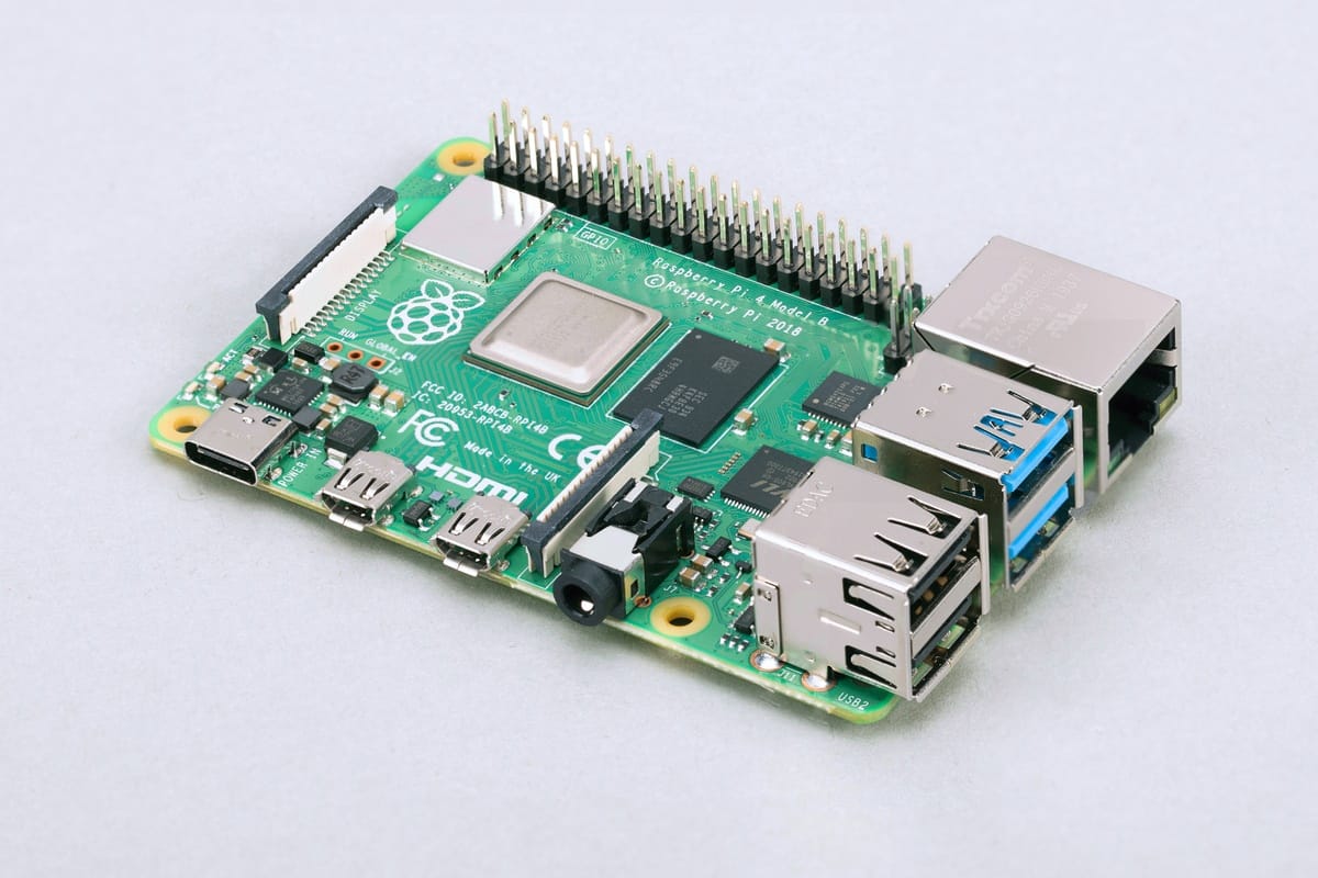
The Raspberry Pi is a single board computer that numbers 4 revisions and a minimalistic zero variant. It is a popular choice for different projects because of its small size, efficient power consumption, processing speed and it being a full Linux based computer.
In this article, I will explain which connection capabilities the Raspberry Pi model 3 and 4 provide, and which functions they natively support (that is, functions that do not require additional HATS extension).
Raspberry Pi Specs
 Source: wikipedia.org
The Raspberry Pi 3B has the following specs:
- Processor: Cortex-A53 Arm v7 4xCores
- SRAM: 1GB
- Clock Speed: 1.4Ghz
- GPIO: 26 digital, 0 analog
The Raspberry Pi 4B has a new processor and more RAM, while the GPIOs stay the same.
- Processor: Cortex-A72 ARM v8 4xCores
- SRAM: 2-8GB
- Clock Speed: 1.45hz
- GPIO: 26 digital, 0 analog
Digital Pins
 Source: raspberrypi.org
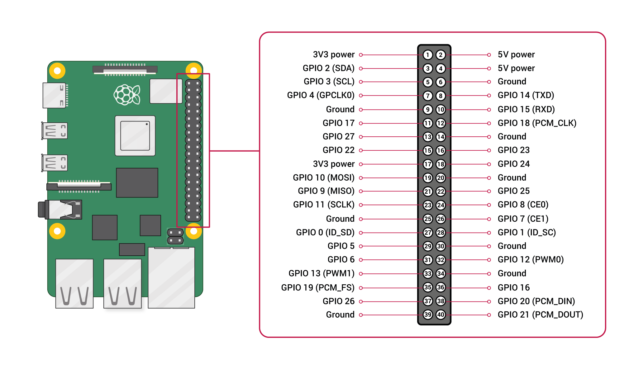
The Raspberry Pi has a total amount of 24 GPIO pins. The pins can be programmed with different libraries. In the following explanation, the officially endorsed Python library gpiozero will be used to show examples.
Digital Input
As a default value, the GPIO pins are not activated at all. You can configure them to be active input devices by using the class gpiozero.DigitalInputDevice. To define a particular pin, use DigitalInputDevice(pinNumber).
With the Gpiozero library you cannot actively read the Pin states, but there are two event handlers to capture changes in the pin’s logic state when_activated will be called when the pin becomes active, and when_deactivated for the compound state. You define custom functions and pass them to these event handlers to implement the desired behavior.
Digital Output
Digital pins are by default turned off. To start emitting signals, you need to activate them.
Output pins are defined with the class gpiozero.DigitalOutputDevice. To define an output pin, use DigitalOutputDevice(pinNumber).
Digital pins can have two states: True or false, which translates to applying a high voltage of 5V, or of 0V. These sates are triggered by using the DigitalOutputDevice.on() or DigitalOutputDevice.off() method.
Analog Pins
The Raspberry Pi has no analog pins. To output analog data, you can use software-based PWM. This will be covered in the section PIN functions.
GPIO Functions
Both the Raspberry Pi3 and Pi4 offer these functions:
- UART: GPIO 10 (RX) and GPIO 8 TX can be used to directly connect two devices with the UART protocol, which enables serial, asynchronous communication.
- I2C: The GPIO 2 SDA and GPIO 3 SCL allow the connection via the I2C protocol. I2C creates a serial, synchronous communication with multiple server/client connection of up to 128 devices.
- SPI: The SPI protocol is a synchronous serial communication between one server and several clients, where both can actively send data. To make an SPI outbound connection, 4 pins are needed. The Raspberry Pi allows to make either 2 separate Server connections, or one server, one client connections. For the 1st GPIO subsystem, GPIO 9, 19, 11, 8 and 16 are used, and for the 2nd GPIO subsystem its 19, 20, 21 and 16.pwm
- PWM: Pulse width modulation is a signaling technique in which a digital signal is switching rapidly between two states - high and low - in a certain frequency. The Raspberry pi has no native support for PWM, but there are Libraries that provide Software PWM, although with restrictions compared to Arduino.
PIN Functions
With the deprecated library WiringPi you can define software-based PWM signals. However, the official documentation states various limitations: Only one pin should be used to output a 100Hz signal, anything else will lead to very high CPU usage and possible frequency drops because of scheduling the libraries function with other functions from the OS.
Conclusion
The Raspberry PI is a power single board computer with an extensive array of 26 GPIO pins. The pins support common standards like UART, I2C and SPI. To program the pins’ behavior, many libraries can be used, mostly written in C or Python. A big difference to Arduino is that all pins on the Raspberry Pi are digital. Software based PWM can be used, but has limitations to real physical PWMs. If you want to process or send analog signals, you need a dedicated HAT extension.