The Raspberry Pi Pico, or shorthand Pico, is a new microcontroller from the Raspberry Pi foundation. From its hardware side, it provides a dual core ARM processor, 2MB of flash memory, and 26 GPIO pins. From its software side, it offers an extensive C/C++ SDK as well as a port of MicroPython.
This article details the Pico’s hardware, its digital and analog pins, and the pin functions it offers.
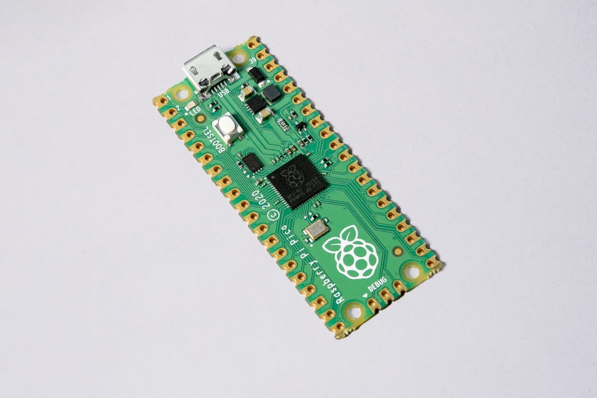
Pico
 Source: raspberrypi.org
The Pico has these specifications:
- Processor: Dual Core Cortex M0+
- Flash Memory: 2MB
- SRAM: 264 KB
- ClockSpeed: 133Mhz
- GPIO: 26 (22 digital, 3 analog, 1 builtin LED)
Digital Pins
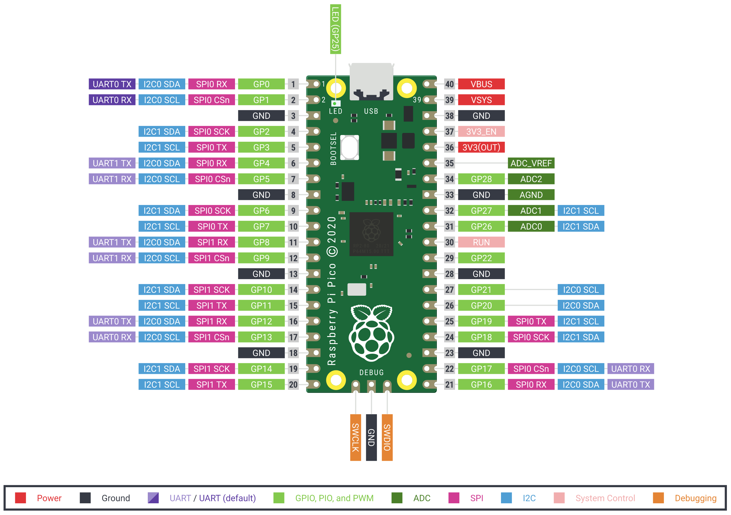 Source: koffler.info
There are 23 digital GPIOs, GP00 to GP22. Also, if desired, the analog pins GP26-28 can be used as digital pins.
Digital Input
Digital Pins are output by default. To set them explicitly, the statement gpio_set_dir(pinNumber, GPIO_IN). Binary values are interpreted as 1 and 0 respectively. The current value can be read with gpio_get(pinNumber).
Digital Output
The digital Pins can be configured as binary output by executing gpio_set_dir(pinNUmber, GPIO_OUT). Binary values are written with gpio_put(pinNumber, value), where value is simply 0 or 1.
Analog Pins
3 pins - GP26, GP27, and GP28 can be used as ADC - Analog to Digital Converters.
Technically, the Pico has two more analog pins: GP28 / ADC3outputs the reference voltage for all analog pins, it can be used to fine-tune the ADC samples or force the power supply into PWM mode, reduce interference of the ADC pins. And ADC4, for which no breakout pin exists, can be used to measure the temperature of the processor.
Analog Input
The analog pins need to be configured with a series of statements.
First, you initialize the ADC - Analog to Digital - hardware. You then reset the targets pins, and configure it to serve as an analog pin. Finally, you can read the 12-bit analog signal.
#include <hardware/gpio.h>
#include <hardware/adc.h>

int main() {
  adc_init();
  adc_gpio_init(PIN_NUMBER);
  adc_select_input(PIN_NUMBER); //pin number 0-3
  uint16_t result = adc_read();
}
You can also read multiple analog pins at the same time by using adc_set_round_robin(bitPattern), where bitPattern defines the particular pins you want to read from.
Analog Output
The Pico can output 12Hz PWM signals in up to 8 blocks of two pins, giving an impressive 16 pin total output capacity.
Configuring output pins requires a few steps. First, you define the pin to serve as PWM output. Then, you do not configure this pin directly, but the “slice” to which it belongs. The characteristics of the PWM is determined by the number of cycles in each pulse, and the fractions between a high and low voltage output. Finally, you involve the PWM signal.
Here is a complete example:
#include <hardware/pwm.h>

gpio_set_function(PIN_NUMBER, GPIO_FUNC_PWM);
int SLICE_NUMBER =  `gpio_pwm_to_slice(PIN_NUMBER);

pwm_set_wrap(SLICE_NUMBER, NR_OF_CYCLES); //Total number of cycles
pwm_set_chan_level(SLICE_NUMBER, PWM_CHAN_A, 1); // HIGH Output
pwm_set_chan_level(SLICE_NUMBER, PWM_CHAN_B, 5); // LOW Output

pwm_set_enabled(SLICE_NUMBER, true);
GPIO Functions
The Pico offers a great amount of flexibility: Most GPIO functions and protocols can be configured to support different protocols. The exact details which pin support what can be found in the official documentation, section 2.19.2. Function Select.
To set a specific function:
#include <hardware/gpio.h>

int main() {
  gpio_set_function(pinNumber, functionEnum)
}
The functionEnum can take any of the following values:
enum gpio_function { GPIO_FUNC_XIP = 0, GPIO_FUNC_SPI = 1, GPIO_FUNC_UART = 2, GPIO_FUNC_I2C = 3, GPIO_FUNC_PWM = 4, GPIO_FUNC_SIO = 5, GPIO_FUNC_PIO0 = 6, GPIO_FUNC_PIO1 = 7, GPIO_FUNC_GPCK = 8, GPIO_FUNC_USB = 9, GPIO_FUNC_NULL = 0xf }
- XIP: With the Execute In Place function, it is possible to access and modify non-RAM data directly, e.g. flash cards or SSD.
- SPI: The SPI protocol is a full-duplex single server, multiple client protocol for exchanging data.
- UART: The UART Asynchronous serial communication standard is most commonly implemented as RS-232, it provides direct connection between two devices.
- I2C: The I2C protocol is a synchronous, multi-server and multi-client protocol for exchanging data.
- PWM: Pulse width modulation is a signaling technique in which a digital signal is switching rapidly between two states - high and low - in a certain frequency. 16 PWM channels are available.
- SIO: Access the internal CPU registers.
- PIO0 & PI01: The PIO Programmable I/O Hardware Subsystem allows to write efficient code to access any new hardware, similar to FGPA and CPLD in other hardware architectures. The Pico has two PIO systems, and pins can be set to “join” these systems when accessing hardware.
- GPCK: Allows to access the Pico’s internal clock.
- USB: At the time of writing, I could not figure out how to use this mode.
In addition to the many functions, you can also set the interrupt level of the pins with gpio_set_irq_enabled(pinNumber, eventsBitmask, 1), where the events bit mask refers to LEVEL_LOW, LEVEL_HIGH, EDGE_FALL and EDGE_RISE.
Conclusion
The Raspberry Pico offers unique microcontroller concepts. The flexibility in GPIO usage together with the new PIO system provide opportunities to attach many different forms of hardware. It will be interesting to see how the developer community will use these opportunities.