
When I started my project to create a robot, I had only a vague idea of the required computer hardware. Reading about other robot projects, Arduino and Raspberry Pi are mentioned. Both are important computers, but for very different purposes. In my microcontroller blog series, I want to investigate Arduino, Raspberry PI, their hardware functions and connection options.
The Arduino is a real go-getter of do-it-yourself projects. Since its inception 2012 it has provided the platform for countless hobbyist’s projects, from home appliances, IOT to robots. Different hardware revisions exist, yet the most common one is the classic Arduino Uno Rev3.
This article details the hardware, GPIO pins, and the supported connection protocols of the Arduino Uno.
Arduino Uno Rev 3 / Arduino Nano
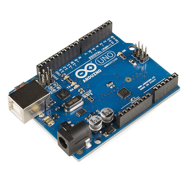 Source: wikipedia.org
The Arduino Uno Rev 3 has this hardware:
Microcontroller: ATmega328P / ATmega328P Flash Memory: 32KB SRAM: 2KB EEPROM: 1KB ClockSpeed: 16MhZ GPIO: 20 (14 digital, 6 analog)
Digital Pins
The Arduino has 14 digital pins that can be used as input or output pins.
Digital Input
All digital pins are configured as output pins by default. However, they can be explicitly configured with the method setPinMode(pinNumber, mode), where mode is either INPUT or INPUT_PULLUP.
The input state - which is translated to true/false bases on the voltage - are HIGH and LOW. To obtain the state, use the method digitalRed(pinNumber). The mode INPUT_PULLUP reverses the values of HIGH and LOW, and the receiving end of the wire should be connected to ground.
Digital Output
To output a digital signal, the Pins need to be configured with the method pinMode(pinNumer, OUTPUT). To write a value, the method digitalWrite(pinNumber, Value), where value is either HIGH or LOW.
Analog Pins
The Arduino has 6 analog pins.
Analog Input
Input mode is also the default behavior of analog pins. The Arduino board uses a 10bit analog-to-digital converter, delivering the values 0 to 1023. These pins can be configured explicitly with setPinMode(pinNumber, mode). With analogRead(pinNumber, the current signal value can be read. If the pin mode is set to INPUT_PULLUP, the obtained values will be influenced.
Analog Output
Because the Arduino board has no digital to analog converter, the analog pins can only be configured as digital output pins with setPinMode(pinNumber, OUTPUT), where the pin number is prefixed with an A.
GPIO Functions
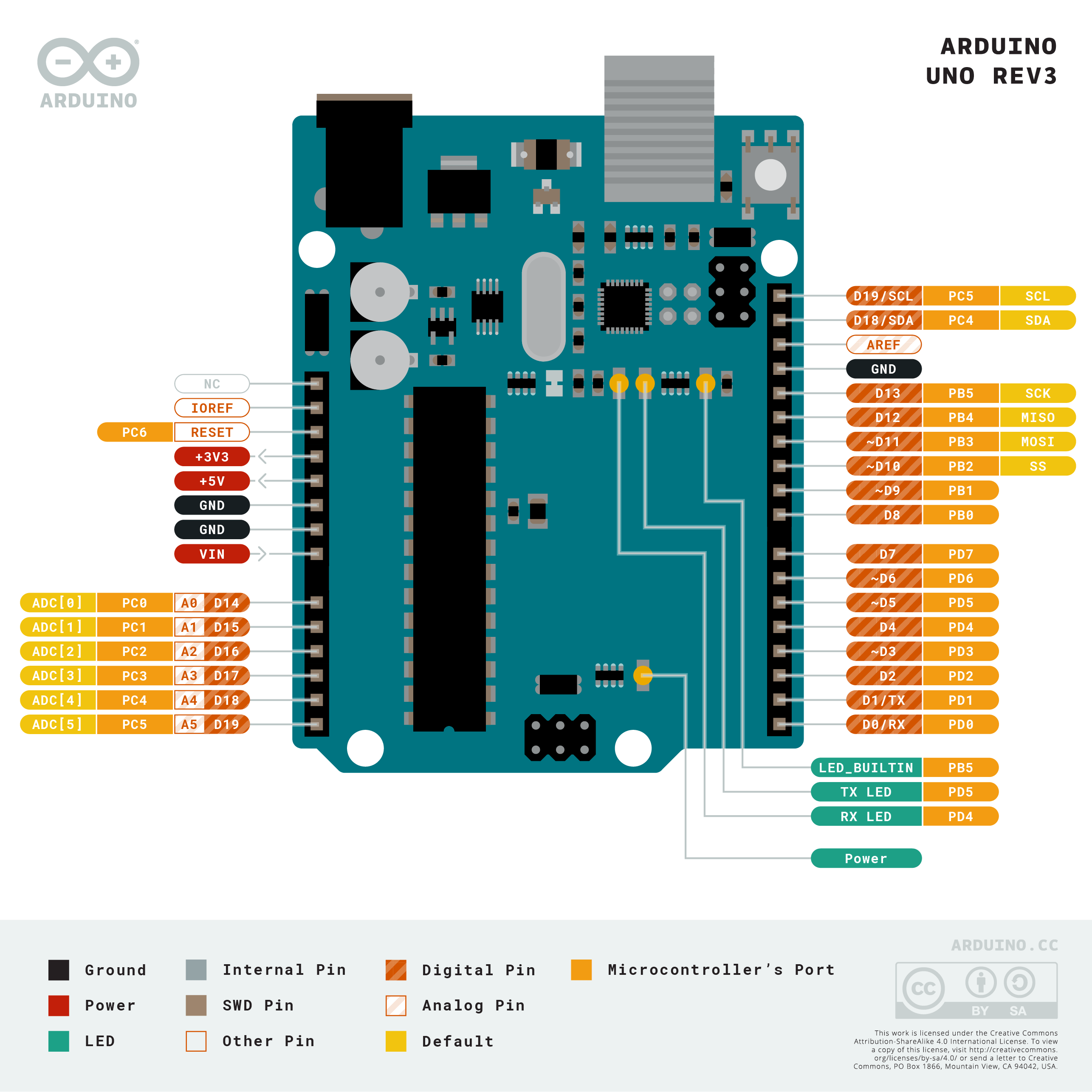 Source: Arduino Store
The Arduino provides the following functions via its pins:
- PWM: Pulse width modulation is a signaling technique in which a digital signal is switching rapidly between two states - high and low - in a certain frequency. Pins 3, 5, 6, 9, 10, 11 can be used for PWM. The available modulation patterns are caped by the Arduinos AT32P clock rate of 1000Hz
- UART: Digital Pins 0 (RX) and DP 1 TX can be used to directly connect two devices with each other. The UART protocol creates a serial connection, data is transmitted asynchronously, and the data is times with a clock signal along the one wire. Technically, the UART connection can also be established via the USB port - the Arduino has a built-in serial to USB converter.
- I2C: The SCL and SDA Pins can be used to connect the Arduino to an I2C bus. The I2C protocol also creates a serial connection, but enables multiple server/client connection of up to 128 devices. The protocol is standardized, yet different implementation with different command subsets exist. The communication flow is typically initiated by the server: Actively polling the clients for new data.
- SPI: The SPI protocol is a synchronous serial communication between one server and several clients, where both can actively send data. SPI is a common protocol for interfacing with sensors. The Arduino provides pins for two different SPI bus: The dedicated ICSP pins, and DP 10 to 13
Pin Types
In addition to the explained protocols, there is another category of pins: Interrupt pins. In normal, uninterrupted program flow, the Arduino runs its program continuously, without end. When an interrupt pin becomes active, this program flow is stopped to call an interrupt handler. To use this feature, the pins need to be explicitly programmed with
The final pin type is interrupt pins, they allow incoming signals to gain priority over the microcontrollers current function. Interrupts are defined with attachInterrupt(vectorNumber, callbackFunction, CHANGE). The vectorNumber references special space in the Arduinos memory, and when this memory changes, the callback function is executed. Only pins 2 and 3 can be configured as interrupt pins.
Conclusion
The Arduino is the established work horse of many do-it-yourself projects. Despite its age of almost 10 years, it is versatile, fast, cheap and has a huge catalog of libraries to interface many different types of hardware. This article detailed the GPIO pins of the Arduino: Its digital and analog pins, how to set and read data, and finally, which protocol It supports. In the next article, I will investigate the GPIO of the Raspberry Pi.