RADU is the code name for my robot project. In the last article of this series, I presented the bill of material, the type and number of items that I want to use in assembling the robots. Since this inception, I tried several sensors individually, and then gradually combined them.
This article is a reflection on this early design stage. I introduce the main components, and explain how they are used in RADU and what particular challenges I encountered during using them.
Arduino Nano
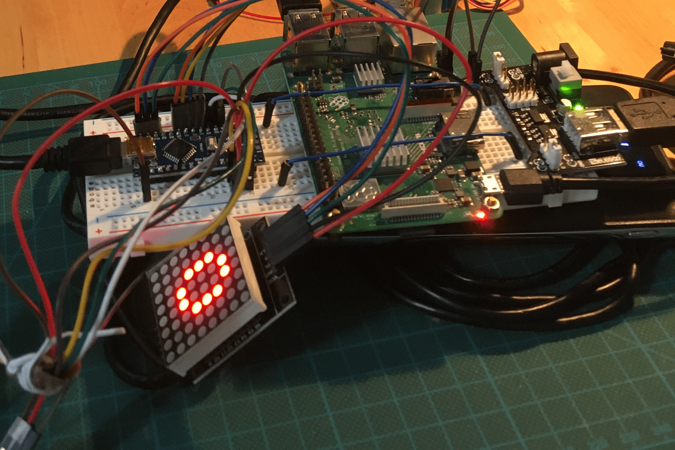
The central micro controller is a trusty Arduino Nano. It resides on a breadboard, and from this it connects to all the other sensors around it. It is powered via a USB connection to the Raspberry Pi 3.
The micro controller provides a simple command line interface when booted:
Boot Menu
START
Using library version 3.0.3/RAD10_chassis_prototype.cpp from Mar 13 2021

+++ RADU MKI v0.4 Booting +++
Please select a command:
- LED {msg}   Print msg to LED Matrix
- DRIVE {dir} Drive in direction
- EXIT        Restart the program
When connected via Serial input, these commands execute various functions of the prototype. All recognized commands will also output a small log message via serial. And this log message will be recorded by the Raspberry Pi - see the next section.
Raspberry Pi 3
The onboard SMC provides two functions for the first RADU prototype.
The first function is to have a remote connection: Serial-over-SSH-over-WIFI. When booted, the Raspberry Pi connects to my local WIFI. Using SSH, I can connect to the Pi, and then open a serial console to the connected Arduino. This allows me to execute the serial commands remotely.
$> ssh devcon@192.168.2.212
Linux raspi-3-2 5.4.83-v7+ #1379 SMP Mon Dec 14 13:08:57 GMT 2020 armv7l

Last login: Sat Mar 13 19:13:44 2021 from 192.168.2.200

devcon@raspi-3-2:/home/devcon $ picocom -b 9600 --omap crcrlf /dev/ttyUSB0
picocom v3.1

port is        : /dev/ttyUSB0
flowcontrol    : none
baudrate is    : 9600
parity is      : none
....
Terminal ready
...
START src/RAD10_chassis_prototypbrary version 3.0.3
+++ RADU MKI v0.4 Booting +++
Please select a command:
- LED {msg}   Print msg to LED Matrix
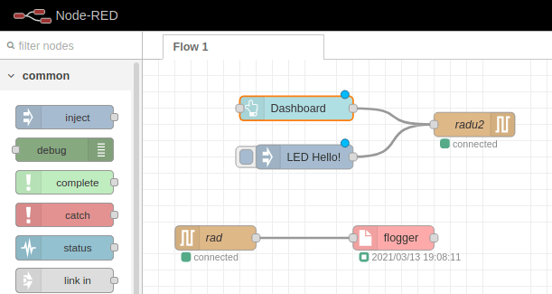
The second function is to listen and log all messages of the serial interface. For this, I use the IOT Software NodeRed, which provides a graphical editor to define streams of data, such as "read serial data, convert to JSON, write to a log file". Here is an example for such a stream:

And once deployed, I collect all RADU status messages in a local logfile, allowing for later data analysis.

LED Matrix
My prototype should give visual feedback to what it is doing. For this, I used a Matrix LED, a gutter of LEDS in which individual dots can be lighted. When used correctly, you can print any ASCI char on it.
Getting this hardware to work gives me several pleasant memories. First, I remember about studying the code base, taking a look at several examples how to print chars to it. The matrix can be controlled by providing a bit mask of the individual LEDs: Which one should be turned on, which one should be off? And with this on/off switches, signs and letters can be printed on the matrix.
But how to convert a character to a bitmask? The first piece of the puzzle is to convert the character into its ASCI code value. The second piece is to have an array in which the bitmasks of all chars are stored, and where the array index corresponds to the ASCI value of the character. And the third piece is to use the stringcpy function to copy the bitmask from this array to the LED matrix. Figuring this out, and implementing the code, was a very insightful activity.
Here are the relevant parts of the overall program. First, this is an example from the bitmask array for expressing the character A. The value consists of two integers, representing where on the matrix the dots should be drawn, followed by 5 bitmasks for each of the 5x8 rows. In these masks, a 0 expresses off, and a 1 means on for the LED. If your literally turn your head around, you can imagine the pattern that will be shown on the screen.
const unsigned char char_arr[] PROGMEM = {
  //...
  4, 8, B01111110, B00010001, B00010001, B01111110, B00000000 // A
  //...
}
The following function includes the actual printing code. First, it converts the given character to its asci value. Then, it creates a buffer to hold the bitmask data, and then copies by using pointer semantics: Stating at char_arr index 0 + the asci value times 7, it copies all next 7 values, which will be the above shown line. Finally, this is written to the matrix, and after a short delay, the matrix is cleared.
void printCharOnMatrix(char car) {
  int ascii = int(car);

  byte buffer[7];
  memcpy_P(buffer, char_arr + (7 * ascii), 7);

  matrix.writeSprite(2,0,buffer);
  delay(700);
  matrix.clear();
}
It was a truly remarking event when I first saw a complete word flashing by, character by character.
IR Control
In addition to the serial commands, I also wanted an immediate control of the robot. This is achieved with an Infrared Sensor and a TV remote control. On the control, I have a direction wheel which translates to up-down and left-right commands - when this is used, RADU should move accordingly. In additions, I also capture all keys on the number pad. The IR code was easy to write - read the details in my blog post about IR commands. In this version of the RADU prototype, I just show the pressed button on the LED display.
Status LED
The final piece of equipment that is added to RADU is a small, self-designed perf-board with a RGB LED. Different colors signal different status. During booting and when processing a command, the LED turns blue. If RADU is ready to receive commands, the LED is green. IF some form of error happens, the LED turns red.
The implementation is straight forward: Each color can be set with one method, which will configure the output pins accordingly. For example, to set the LED to green, the following code is used:
void StatusLED::set_green() {
  digitalWrite(A3, LOW);
  digitalWrite(A4, HIGH);
  digitalWrite(A5, LOW);
}

StatusLED led{};
RADU Box
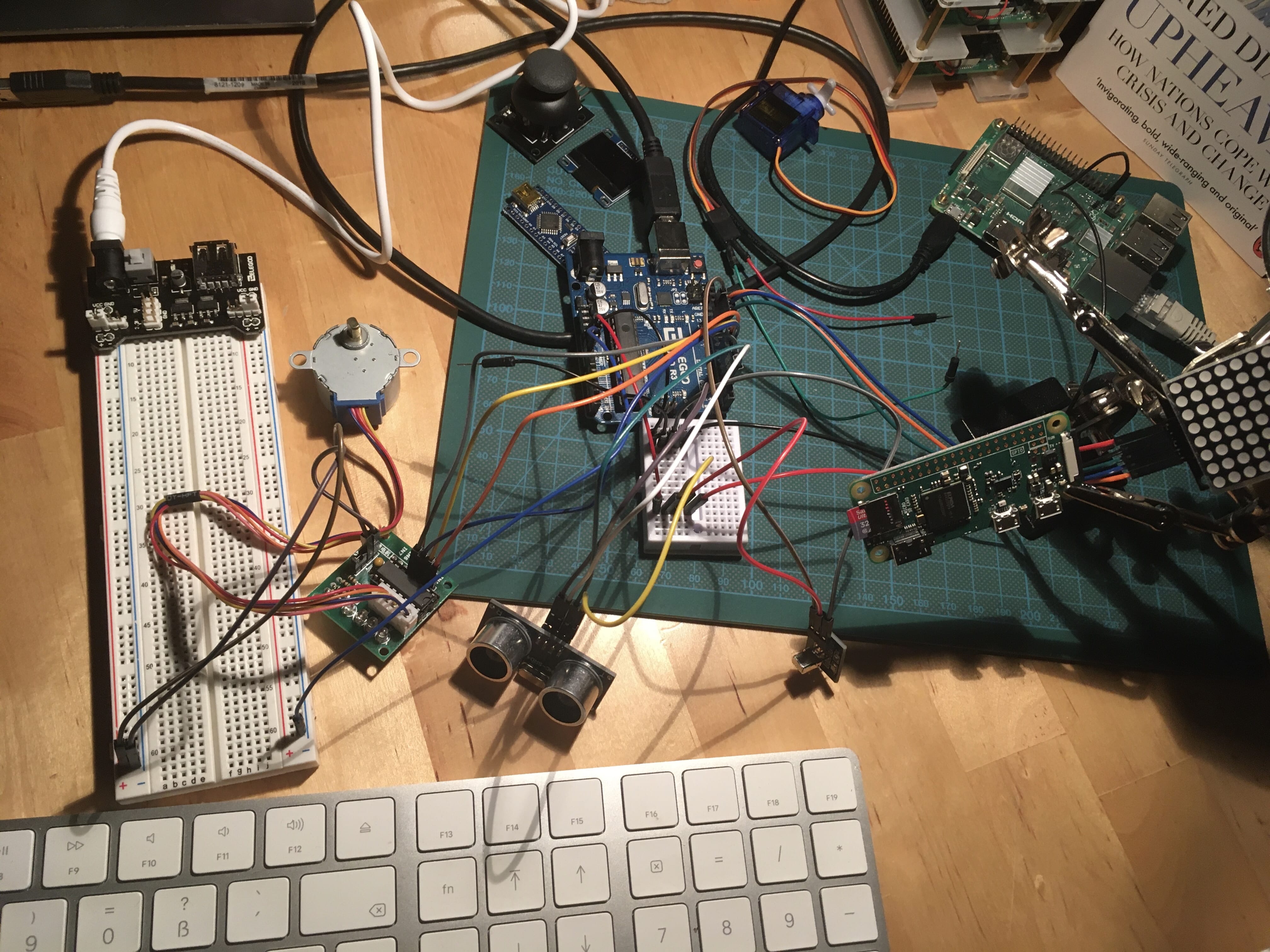
With all sensors tried individually, the next step is to put them all together. I simple call it a box. It’s actually more an agglomerate of the different sensors, spread out flat on interconnected breadboards, wired to the Arduino which is connected to the Raspberry Pi. And all around, loose sensors, wires, and the self-soldered perf-board with the RGB LED.

Its debatable whether this really is a prototype, or not just a mess of things. However, this prototype is my first build. All of the components are important for the final robot, so getting used to use them, and including them in one Arduino program, is an important step.
Conclusion
This article explained how I gradually used single board computer, micro controller units and sensors to build up a unique collection for the first prototype. Let’s repeat the essential steps. The Raspberry Pi is the brain of the robot, it provides wireless access to the robot, and it logs messages send from connected Arduino. The Arduino is the controller: It controls the IR sensors, the LED matrix, and it will also control the motors. The combined sensors honestly look like a big mess. In the next article, I will attach them to chassis, connect motors, and will build the first movable prototype of RADU.
