IOT@Home: RP2040W Home Assistant Integration
—
ESPHome is an amazing tool that simplifies adding various sensor to your IOT@Home. A novel feature is that it not only supports ESP8266 and ESP32 boards, but also boards based on the RP2040, first arriving in the form of the Raspberry Pi Pico. While the original RP2040 was without any Wi-Fi capabilities, a later released variant added Wireless capabilities. I was curious to see an RP2040 W board with Home Assistant added to my sensor network, and to understand if there are any limitations when using this board.
The technical context of this article is ESP Home 2024.10 and a Raspberry Pico 2080W. All examples should work with newer software version and boards with the same chipset as well.
RP2040 in Home Assistant
The RP2040 is a powerful and GPIO rich microprocessor. I covered this microcontroller extensively in an earlier article. In addition to a great number of digital pins whose protocols can be even changed and configured at runtime, the board can also be programmed with three different frameworks: The Raspberry Pico C Library, MicroPython, and Arduino C (but only on the Nano RP2040 Connect board).
Searching the current status of RP2040 W integration with ESP Home, I found the excellent blog article Using ESPHome on the Raspberry Pi Pico W and other RP2040 microcontroller boards. Its author gives detailed technical explanation, experiences, and highlights the current limits. Since the RP2040 pin configuration is essentially determined and runtime configured, and it provides several bus systems for SPI and I2C, the ESP Home integration makes some assumptions which pins you are using. From this article, the most important limit is this: Only the I2C bus 0 is supported, which means GP00 & GP01, GP11 and GP12, GP12 and GP13, GP20 and GP21 can be used.
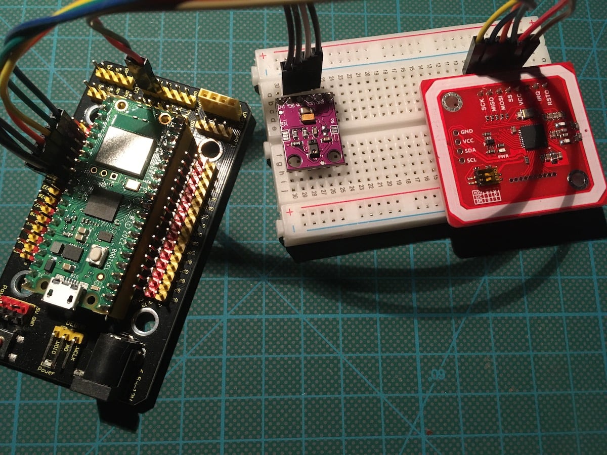
Based on this encouraging news, I started with integrating a bare-bones Raspberry Pico RP2040 W with ESP Home, and then added a light sensor and RFID reader. Here are my experiences.
The final result is this:
ESP Home Device Configuration
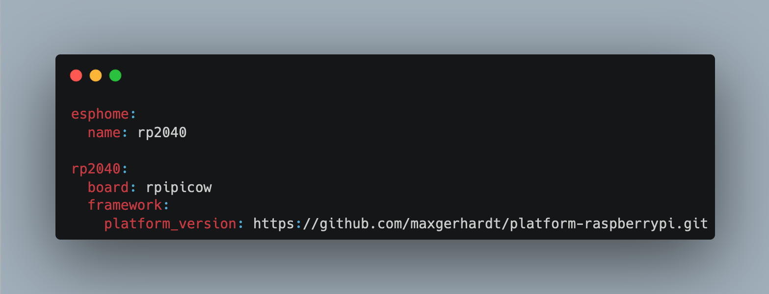
It all starts with a familiar device configuration stanza. You can either create a new board with the ESP Home configuration wizard, or use the following configuration stanza:
esphome:
  name: rp2040

rp2040:
  board: rpipicow
  framework:
    # Required until https://github.com/platformio/platform-raspberrypi/pull/36 is merged
    platform_version: https://github.com/maxgerhardt/platform-raspberrypi.git
Flashing the device for the first time is different from an ESP-based device, but will be familiar when you worked with the RP2040W in other projects: The resulting binary is an UF2 file that needs to be uploaded to the RP2040W board when it is connected in USB mode. Afterwards, it reboots and starts to output logs via serial or to ESP Home via Wi-Fi.
Adding a Light Sensor
To see how other sensors can be integrated with an RP2040 board, I added a spare ADPDP9960 light sensor to it. The relevant ESP Home configuration is as shown:
i2c:
  sda: 20
  scl: 21

apds9960:
  address: 0x39
  update_interval: 5s
  proximity_gain: 8x
  ambient_light_gain: 16x
  gesture_led_drive: 100mA
  gesture_gain: 8x

sensor:
  - platform: apds9960
    type: CLEAR
    name: "APDS9960 Clear"
  - platform: apds9960
    type: RED
    name: "APDS9960 RED"
  - platform: apds9960
    type: GREEN
    name: "APDS9960 Green"
  - platform: apds9960
    type: BLUE
    name: "APDS9960 Blue"
  - platform: apds9960
    type: PROXIMITY
    name: "APDS9960 Proximity"
Following the initial flashing of the board, all subsequent updates are via OTA. Here is the log output:
INFO Reading configuration /config/rp2040.yaml...
INFO Generating C++ source...
INFO Compiling app...
Processing rp2040 (board: rpipicow; framework: arduino; platform: <https://github.com/maxgerhardt/platform-raspberrypi.git>)
--------------------------------------------------------------------------------

HARDWARE: RP2040 133MHz, 264KB RAM, 2MB Flash

- framework-arduinopico @ 1.20602.0 (2.6.2)
- tool-rp2040tools @ 1.0.2
Flash size: 2.00MB
Sketch size: 1.00MB
Filesystem size: 1.00MB
Maximium Sketch size: 1044480 EEPROM start: 0x101ff000 Filesystem start: 0x100ff000 Filesystem end: 0x101ff000
LDF: Library Dependency Finder -> <https://bit.ly/configure-pio-ldf>
Dependency Graph
|-- WiFi @ 1.0.0
|   |-- Updater @ 1.0
|   |   |-- MD5Builder @ 1.0.0
|   |   |-- LittleFS @ 0.1.0
|   |   |-- PicoOTA @ 1.0.0
|   |   |   |-- LittleFS @ 0.1.0
|   |-- MD5Builder @ 1.0.0
|   |-- lwIP-Ethernet @ 1
|   |   |-- lwIP_CYW43 @ 1
|   |   |   |-- SPI @ 1.0
|   |   |-- SPI @ 1.0
|   |-- lwIP_CYW43 @ 1
|   |   |-- SPI @ 1.0
|   |-- SPI @ 1.0
|-- LEAmDNS @ 1.2
|   |-- lwIP-Ethernet @ 1
|   |   |-- lwIP_CYW43 @ 1
|   |   |   |-- SPI @ 1.0
|   |   |-- SPI @ 1.0
|   |-- WiFi @ 1.0.0
|   |   |-- Updater @ 1.0
|   |   |   |-- MD5Builder @ 1.0.0
|   |   |   |-- LittleFS @ 0.1.0
|   |   |   |-- PicoOTA @ 1.0.0
|   |   |   |   |-- LittleFS @ 0.1.0
|   |   |-- MD5Builder @ 1.0.0
|   |   |-- lwIP-Ethernet @ 1
|   |   |   |-- lwIP_CYW43 @ 1
|   |   |   |   |-- SPI @ 1.0
|   |   |   |-- SPI @ 1.0
|   |   |-- lwIP_CYW43 @ 1
|   |   |   |-- SPI @ 1.0
|   |   |-- SPI @ 1.0
|-- Updater @ 1.0
|   |-- MD5Builder @ 1.0.0
|   |-- LittleFS @ 0.1.0
|   |-- PicoOTA @ 1.0.0
|   |   |-- LittleFS @ 0.1.0
|-- noise-c @ 0.1.4
|   |-- libsodium @ 1.10018.1
|-- Wire @ 1.0
|-- MD5Builder @ 1.0.0
Compiling .pioenvs/rp2040
Be warned: Compilation took more than 10 minutes on an older Raspberry Pi 4 that runs my Home Assistant stack.
Immediately after booting, I could see that the I2C connection worked:
INFO Reading configuration /config/rp2040.yaml...
INFO Starting log output from rp2040.local using esphome API
INFO Successfully connected to rp2040.local
...
[10:44:46][C][i2c.arduino:052]: I2C Bus:
[10:44:46][C][i2c.arduino:053]:   SDA Pin: GPIO20
[10:44:46][C][i2c.arduino:054]:   SCL Pin: GPIO21
[10:44:46][C][i2c.arduino:055]:   Frequency: 50000 Hz
[10:44:46][C][i2c.arduino:064]:   Recovery: failed, SDA is held low on the bus
[10:44:46][I][i2c.arduino:068]: Results from i2c bus scan:
[10:44:46][I][i2c.arduino:074]: Found i2c device at address 0x39
[10:44:46][C][apds9960:124]: APDS9960:
[10:44:46][C][apds9960:125]:   Address: 0x39
[10:44:46][C][apds9960:127]:   Update Interval: 60.0s
An shortly after, I could see the sensor readings too:
[11:00:52][D][sensor:126]: 'APDS9960 Clear': Sending state 0.04120 % with 1 decimals of accuracy
[11:00:52][D][sensor:126]: 'APDS9960 RED': Sending state 0.01678 % with 1 decimals of accuracy
[11:00:52][D][sensor:126]: 'APDS9960 Green': Sending state 0.01678 % with 1 decimals of accuracy
[11:00:52][D][sensor:126]: 'APDS9960 Blue': Sending state 0.01526 % with 1 decimals of accuracy
[11:00:52][D][apds9960:206]: Got proximity=1.2%
This was quite astonishing! The familiar ESP Home experience "configure and flash" worked with the same ease as if using an esp8266 board.
However, I encountered one limitation of the ADPS9960 light sensor. On paper, it also allows the detection of simple gestures (up, down, left, right). Adding this functionality was a perplexing and ultimately failed attempt. Although correctly configured with ESP Home following the official documentation example down to the last piece of whitespace, I could not get any sensor readings. Even leaving the scope of this article, trying to program the RP2040 W with two different MicroPython libraries, and even using Arduino-C with an esp8266, I could not get any readings from this sensor. Searching for error sources, I stumbled upon a thread in which others said that some cheap sensor just doesn’t provide gestures readings, probably because they are just copies without the appropriate hardware register. At this point, I gave up to integrate ADPS9960 gesture recognition in ESP Home.
RFID
My second sensor of choice is an PN532 RFID reader, connected via SPI.
As before, the Home Assistant configuration need to contain a stanza for the bus and for the sensor. Here it is:
spi:
  - id: spi_bus0
    clk_pin: 18
    mosi_pin: 19
    miso_pin: 16

binary_sensor:
  - platform: pn532
    uid: CA-41-90-81
    name: "PN532 NFC Tag"

text_sensor:
  - platform: template
    name: "RFID Tag"
    id: rfid_tag

pn532_spi:
  cs_pin: 17
  update_interval: 1s
  on_tag:
    then:
    - text_sensor.template.publish:
        id: rfid_tag
        state: !lambda 'return x;'
An OTA update later, the logs showed the successful bus initiation as well as detecting the connected RFID reader:
[11:16:02][C][spi:101]: SPI bus:
[11:16:02][C][spi:102]:   CLK Pin: GPIO18
[11:16:02][C][spi:103]:   MISO Pin: GPIO16
[11:16:02][C][spi:104]:   MOSI Pin: GPIO19
[11:16:02][C][spi:106]:   Using HW SPI: NO
[11:16:02][C][pn532:347]: PN532:
[11:16:02][C][pn532:359]:   Update Interval: 1.0s
[11:16:02][C][pn532:362]:   Tag 'PN532 NFC Tag'
[11:16:02][C][pn532_spi:156]:   CS Pin: GPIO17
The RFID functionality implemented in this example is purely for reading the id tags:
[11:16:30][D][pn532:280]: Mifare classic
[11:16:30][E][pn532.mifare_classic:095]: Authentication failed - Block 0x04
[11:16:30][D][pn532:162]: Found new tag '37-62-D6-B5'
[11:16:30][D][pn532:295]: Waiting to read next tag
RFID readers provide more features than just reading an ID tag. The ESP Home documentation shows how to read data written with the Home Assistants companion app which creates NDEF data. I did not venture down this road, and stayed with just reading tag IDs for different automation purposes.
Home Assistant Dashboard Integration
With the board operational, lets head over to Home Assistant, and add the new board via "Settings" => "Devices & Services", then click the button "Add Integration" and enter the device IP and configured password. The next screen shows all configured entities of the board, and with one more click, a new dashboard card is shown.
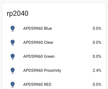
After 24 hours of data collection, I could see the following data for the clear channel of the light sensor:
![]()
Complete Home Assistant Configuration
Here is the complete Home Assistant configuration for an RP2040 W with the APDS9960 light sensor and an RFID PN532 reader:
esphome:
  name: rp2040

rp2040:
  board: rpipicow
  framework:
    # Required until https://github.com/platformio/platform-raspberrypi/pull/36 is merged
    platform_version: https://github.com/maxgerhardt/platform-raspberrypi.git

# Enable logging
logger:

# Enable Home Assistant API
api:
  encryption:
    key: "SECRET"

ota:
  password: "SECRET"

wifi:
  ssid: "SECRET"
  password: "SECRET"

i2c:
  sda: 20
  scl: 21

spi:
  - id: spi_bus0
    clk_pin: 18
    mosi_pin: 19
    miso_pin: 16

apds9960:
  address: 0x39
  update_interval: 5s
  proximity_gain: 8x
  ambient_light_gain: 16x
  gesture_led_drive: 100mA
  gesture_gain: 8x

sensor:
  - platform: apds9960
    type: CLEAR
    name: "APDS9960 Clear"
  - platform: apds9960
    type: RED
    name: "APDS9960 RED"
  - platform: apds9960
    type: GREEN
    name: "APDS9960 Green"
  - platform: apds9960
    type: BLUE
    name: "APDS9960 Blue"
  - platform: apds9960
    type: PROXIMITY
    name: "APDS9960 Proximity"

binary_sensor:
  - platform: pn532
    uid: CA-41-90-81
    name: "PN532 NFC Tag"

text_sensor:
  - platform: template
    name: "RFID Tag"
    id: rfid_tag

pn532_spi:
  cs_pin: 17
  update_interval: 1s
  on_tag:
    then:
    - text_sensor.template.publish:
        id: rfid_tag
        state: !lambda 'return x;'
Conclusion
This article explored how to use a Rasperry Pico RP2040W with ESP Home and Home Assistant. The easy setup comfort provided with ESP Home worked just like with an ESP board: Define a board configuration, create the binary, flash the device, and from there on its Wi-Fi connected and allows flawless OTA updates. With the board ready and operational, I added first an I2C device, the ADPDP9960 sensor, and then and SPI device, the PN532 RFID reader. Both worked flawlessly as well, reading showed up in log files, and Home Assistant dashboards were added in mere minutes. From this experience, I can highly recommend to use RP2040W boards with ESP Home too.