
When you build a robot, there are basically two approaches: You can either start from scratch, get all required hardware, the chassis, sensor, actuators and microcontroller or single-board computers, and program the software. Or you buy a complete kit which includes all parts and a software stack.
In 2021, I started a project to build a self-navigating pickup-and-deliver robot. I created two robots from scratch. RADU MK1 is based on Arduino and controlled via IR. RADU MK2 is a combination of Raspberry Pi and Raspberry Pico, running ROS and accepting movements commands via this robotic middleware. Building a moving robot - although not a self-navigating one - felt completed.
Then, to jumpstart my understanding and skill about robotic arms, I tested a complete robotic arm kit. Once assembled, I wrote a Python script that directly executes movements options. This was a pleasant surprise, and I considered other robotic kits. How about choosing a kit for a moveable robot that has a manipulator on top?
This article introduces the Raspberry Pi Tank Kit and how I re-wrote the basic software so that it works on an Ubuntu Server 20.04 OS. You will learn about necessary patches, about auto starting, and about modifying the frontend.
RaspTank Robotic Kit
The Raspberry Pi Tank comes as a complete kit with all parts, construction tools, and software. It moves on two tracks, has a distance sensor and a Raspberry Pi camera mounted in front. Furthermore, it features a 3 DOF gripper that can interact with objects directly in front of the tank. This kit is the second one from the same company, because I had a good experiences with the robot manipulator as explained in a previous article.
Once assembled and configured, the tank can be operated from an intuitive web GUI from any connected computer in the same network. However, in my robot project, I want to use the Robot Operating System ROS to control it. And here it became difficult. The robots control software is tailored towards the Raspberry Pi OS. But getting ROS to run means to compile everything from scratch. Therefore, I switched to Ubuntu Server 20.04 where ROS runs without problems, but now the robot control software did not work without additional setups.
Part 1: Assembly
Assembling this robot was not as challenging as my experience with the mobile gripper. Of course, this factors in the very point that I gained experience. The positive point I want to mention is that the manual instructs you very early to connect all servo motors for an initial calibration. The robot software starts briefly, rotates all servo motors to their natural 90-degree orientation, and turns off. Then, you can continue the assembly with all servo motors correctly oriented, entirely eliminating the tedious disassembling of the arm joints that I had with the robot arm model.
Considering the camera, be sure to pull the camera cable though the shield, then fix the camera cable in the Raspberry Pi, and then fix the motor shield to the Raspberry Pi.
Part 2: Installing Required Libraries
Following the installation manual, you basically copy the official source code, execute a setup script, and then start a local web server that opens a web frontend for controlling the robot. But because we switched from Raspberry Pi OS to Ubuntu Server, this initial startup does not work. Specifically, I encountered the following errors
 ./startup.sh
Traceback (most recent call last):
  File "//home/pi/adeept_rasptank/server/webServer.py", line 26, in <module>
    import app
  File "/home/pi/adeept_rasptank/server/app.py", line 8, in <module>
    from camera_opencv import Camera
  File "/home/pi/adeept_rasptank/server/camera_opencv.py", line 2, in <module>
    import cv2
  File "/usr/local/lib/python3.7/dist-packages/cv2/__init__.py", line 3, in <module>
    from .cv2 import *
ImportError: libhdf5_serial.so.103: cannot open shared object file: No such file or directory
And this one:
Traceback (most recent call last):
  File "//home/pi/adeept_rasptank/server/webServer.py", line 26, in <module>
    import app
  File "/home/pi/adeept_rasptank/server/app.py", line 8, in <module>
    from camera_opencv import Camera
  File "/home/pi/adeept_rasptank/server/camera_opencv.py", line 2, in <module>
    import cv2
  File "/usr/local/lib/python3.7/dist-packages/cv2/__init__.py", line 3, in <module>
    from .cv2 import *
ImportError: libQtGui.so.4: cannot open shared object file: No such file or directory
To solve these error messages, I needed to modify the names of installed libraries and/or install new libraries, both for the system and specifically with Python Pip.
Part 3: Source Code Modifications
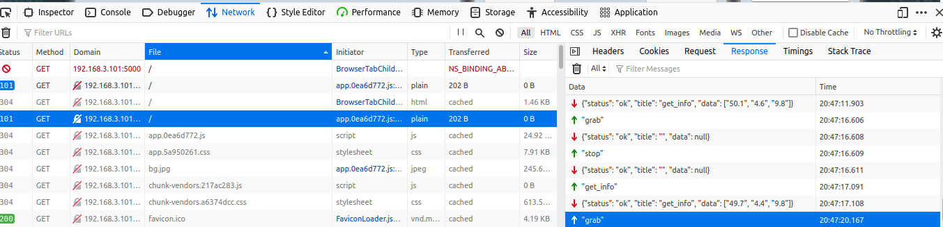
After installing all required system libraries and Python packages, the web GUI still throws several errors. Some errors originate from the Python program on the Raspberry Pi, other errors can be investigated by checking the WebSocket messages exchanged between your browser and the software:
Error 1: Could not determine default I2C bus for platform
The first error encountered is as follows:
sudo python3 server/webServer.py
Traceback (most recent call last):
  File "server/webServer.py", line 14, in <module>
    import RPIservo
  File "/home/pi/adeept_rasptank/server/RPIservo.py", line 17, in <module>
    pwm = Adafruit_PCA9685.PCA9685()
  File "/usr/local/lib/python3.8/dist-packages/Adafruit_PCA9685/PCA9685.py", line 74, in __init__
    self._device = i2c.get_i2c_device(address, **kwargs)
  File "/usr/local/lib/python3.8/dist-packages/Adafruit_GPIO/I2C.py", line 63, in get_i2c_device
    busnum = get_default_bus()
  File "/usr/local/lib/python3.8/dist-packages/Adafruit_GPIO/I2C.py", line 55, in get_default_bus
    raise RuntimeError('Could not determine default I2C bus for platform.')
RuntimeError: Could not determine default I2C bus for platform.
For some reason, you need to define the I2C bus number explicitly on Ubuntu. The change is easy - just pass the parameter (busnum=1) in all places where the I2C bus is accessed.
Here is an example how to patch the file RPIservo.py.
pwm = Adafruit_PCA9685.PCA9685(busnum=1)
pwm.set_pwm_freq(50)
Error 2: Permission Denied for I2C
Here is this particular error message:
Traceback (most recent call last):
  File "server/webServer.py", line 14, in <module>
    import RPIservo
  File "/home/pi/adeept_rasptank/server/RPIservo.py", line 17, in <module>
    pwm = Adafruit_PCA9685.PCA9685(busnum=1)
  File "/usr/local/lib/python3.8/dist-packages/Adafruit_PCA9685/PCA9685.py", line 74, in __init__
    self._device = i2c.get_i2c_device(address, **kwargs)
  File "/usr/local/lib/python3.8/dist-packages/Adafruit_GPIO/I2C.py", line 64, in get_i2c_device
    return Device(address, busnum, i2c_interface, **kwargs)
  File "/usr/local/lib/python3.8/dist-packages/Adafruit_GPIO/I2C.py", line 97, in __init__
    self._bus = Adafruit_PureIO.smbus.SMBus(busnum)
  File "/usr/local/lib/python3.8/dist-packages/Adafruit_PureIO/smbus.py", line 125, in __init__
    self.open(bus)
  File "/usr/local/lib/python3.8/dist-packages/Adafruit_PureIO/smbus.py", line 151, in open
    self._device = open("/dev/i2c-{0}".format(bus), "r+b", buffering=0)
PermissionError: [Errno 13] Permission denied: '/dev/i2c-1'
To resolve this, check first that the I2C subsystem is actually enabled.
cat /boot/firmware/syscfg.txt
# This file is intended to be modified by the pibootctl utility. User
# configuration changes should be placed in "usercfg.txt". Please refer to the
# README file for a description of the various configuration files on the boot
# partition.

enable_uart=1
dtparam=audio=on
dtparam=i2c_arm=on
dtparam=spi=on
cmdline=cmdline.txt
If not, set dtparam=i2c_arm to on, and reboot.
If this is working, then the error is related to user permissions: the device /dev/i2c-1 belongs to the i2cgroup. The default user pi need to be part of this group as well. Execute the following command, and the error will be resolved.
sudo usermod -a -G i2c pi
Error 3: GPIO Error ‘Not running on a RPi!’
The next error is as follows:
RuntimeError: Not running on a RPi!
Searching on the internet, this bug is quite persistent as explained in this lengthy forum entry.
To solve it, first reinstall rpi.gpio.
$> sudo pip3 install rpi.gpio --upgrade
Second, create a new UDEV rule, a new system group, and add the user pi to this group.
sudo touch /etc/udev/rules.d/91-gpio.rules && echo 'KERNEL=="gpiomem", OWNER="root", GROUP="gpio"' | sudo tee /etc/udev/rules.d/91-gpio.rules
sudo groupadd -f --system gpio
sudo usermod -a -G gpio pi
Error 4: Mailbox error
This error appears with the following message:
Failed to create mailbox device
: Operation not permitted
Traceback (most recent call last):
  File "server/webServer.py", line 26, in <module>
    import app
  File "/home/pi/adeept_rasptank/server/app.py", line 8, in <module>
    from camera_opencv import Camera
  File "/home/pi/adeept_rasptank/server/camera_opencv.py", line 16, in <module>
    led = robotLight.RobotLight()
  File "/home/pi/adeept_rasptank/server/robotLight.py", line 38, in __init__
    self.strip.begin()
  File "/usr/local/lib/python3.8/dist-packages/rpi_ws281x/rpi_ws281x.py", line 131, in begin
    raise RuntimeError('ws2811_init failed with code {0} ({1})'.format(resp, str_resp))
RuntimeError: ws2811_init failed with code -9 (Failed to create mailbox device)
This error originates from the NeoPixel Python package. To reproduce it, execute the following Python program.
import RPi.GPIO as GPIO
from rpi_ws281x import *

LED_COUNT    = 16
LED_PIN  = 12
LED_FREQ_HZ = 800000
LED_DMA  = 10
LED_BRIGHTNESS = 255
LED_INVERT  = False
LED_CHANNEL = 0

GPIO.setwarnings(False)
GPIO.setmode(GPIO.BCM)
GPIO.setup(5, GPIO.OUT)
GPIO.setup(6, GPIO.OUT)
GPIO.setup(13, GPIO.OUT)

strip = Adafruit_NeoPixel(LED_COUNT, LED_PIN, LED_FREQ_HZ, LED_DMA, LED_INVERT, LED_BRIGHTNESS, LED_CHANNEL)
strip.begin()
I saw no conclusive result when searching the internet for this issue, such as in this thread or this open issue on Github. Some threads mention the permission to access raw memory on the device. Apparently, it is a very specific problem tight to a very specific library.
At the end, I could not resolve it, and alas continued to use sudo to start the web GUI.
Error 5: Debugging Camera Configuration
Getting the camera to work was not easy. Since also other users of this kit reported about installation troubles, this section includes the concrete error messages and the details of my approach to get them running.
The error message is mundane.
......................pause..........................
Starting camera thread.
[ WARN:0] global ../modules/videoio/src/cap_gstreamer.cpp (480) isPipelinePlaying OpenCV | GStreamer warning: GStreamer: pipeline have not been created
[ WARN:0] global ../modules/videoio/src/cap_v4l.cpp (887) open VIDEOIO(V4L2:/dev/video0): can't open camera by index
Exception in thread Thread-3:
Traceback (most recent call last):
  File "/usr/lib/python3.8/threading.py", line 932, in _bootstrap_inner
    self.run()
  File "/usr/lib/python3.8/threading.py", line 870, in run
    self._target(*self._args, **self._kwargs)
  File "/home/pi/adeept_rasptank/server/base_camera.py", line 94, in _thread
    for frame in frames_iterator:
  File "/home/pi/adeept_rasptank/server/camera_opencv.py", line 427, in frames
    raise RuntimeError('Could not start camera.')
RuntimeError: Could not start camera.
The first step to resolve any error is to use the native tool raspistill. This showed the following error message:
raspistill -o test.jpg
mmal: mmal_vc_component_enable: failed to enable component: ENOSPC
mmal: camera component couldn't be enabled
mmal: main: Failed to create camera component
mmal: Only 76M of gpu_mem is configured. Try running "sudo raspi-config" and ensure that "memory_split" has a value of 128 or greater
As instructed, I decreased the GPU memory. To do this, start sudo raspi-config, then go to System Options, select P2 GPU Memory, and enter 128. After a reboot, we can try to start the camera again. Yet..
$> raspistill -o test.jpg
mmal: mmal_vc_component_enable: failed to enable component: ENOSPC
mmal: camera component couldn't be enabled
mmal: main: Failed to create camera component
mmal: Failed to run camera app. Please check for firmware updates
Now I checked the connection. Disassembling the shield from the Raspberry Pi, and directly connecting the camera worked. Strange. During another internet search, I stumbled over an advice from stackexchange:
As of may 2016, the GPU_MEM=128 is no longer enough. Increasing it from 128 to 144 made the error go away.
After reassembling the camera with the shield, I tried it again, but to no avail. Let’s check that the camera hardware is correctly recognized by the system when the shield is assembled. The two commands are vcgencmd and dmesg.
$> vcgencmd get_camera

supported=1 detected=1
This showed that the camera is connected correctly.
$> dmesg
...
[    8.081440] bcm2835-codec bcm2835-codec: Device registered as /dev/video10
[    8.081509] bcm2835-codec bcm2835-codec: Loaded V4L2 decode
[    8.082143] bcm2835-isp bcm2835-isp: Device node output[0] registered as /dev/video13
[    8.082750] bcm2835-isp bcm2835-isp: Device node capture[0] registered as /dev/video14
[    8.083207] bcm2835-isp bcm2835-isp: Device node capture[1] registered as /dev/video15
[    8.083572] bcm2835-isp bcm2835-isp: Device node stats[2] registered as /dev/video16
[    8.083610] bcm2835-isp bcm2835-isp: Register output node 0 with media controller
[    8.083636] bcm2835-isp bcm2835-isp: Register capture node 1 with media controller
[    8.083658] bcm2835-isp bcm2835-isp: Register capture node 2 with media controller
[    8.083680] bcm2835-isp bcm2835-isp: Register capture node 3 with media controller
[    8.083887] bcm2835-isp bcm2835-isp: Loaded V4L2 bcm2835-isp
[    8.099405] bcm2835-codec bcm2835-codec: Device registered as /dev/video11
[    8.099494] bcm2835-codec bcm2835-codec: Loaded V4L2 encode
[    8.113940] bcm2835-v4l2-0: scene mode selected 0, was 0
[    8.114450] bcm2835-v4l2-0: V4L2 device registered as video0 - stills mode > 1280x720
[    8.116650] bcm2835-codec bcm2835-codec: Device registered as /dev/video12
[    8.116715] bcm2835-codec bcm2835-codec: Loaded V4L2 isp
[    8.121953] bcm2835-v4l2-0: Broadcom 2835 MMAL video capture ver 0.0.2 loaded.
Also, the kernel messages look ok.
At this point, I ran my custom setup command again, did a clean reboot, and then, suddenly, running raspistill works.
Part 4: Adding a Systemd Unit File
The original setup code manipulates existing systemd configuration files. However, I recommend to use a dedicated file. A dedicated service also gives you the option to selectively check its status with systemctl status raspi-tank.servive or see its logfile with journalctl -u raspi-tank.servive.
Add the following content to the file /etc/systemd/system/raspi-tank.servive.
#
# ---------------------------------------
# Copyright (c) Sebastian Günther 2021  |
#                                       |
# Created: 2021-09-30, 21:39:59         |
#                                       |
# devcon@admantium.com                  |
#                                       |
# SPDX-License-Identifier: BSD-3-Clause |
# ---------------------------------------
#
[Unit]
Description=Raspi Tank
Wants=network.target

[Service]
Type=forking
User=sudo
Group=sudo
WorkingDirectory=/home/pi/adeept_rasptank/
ExecStart=/usr/bin/python3 /home/pi/adeept_rasptank/server/webServer.py
KillSignal=SIGINT
Restart=on-failure
RestartSec=40
SyslogIdentifier=TANK
StandardOutput=syslog

[Install]
WantedBy=multi-user.target
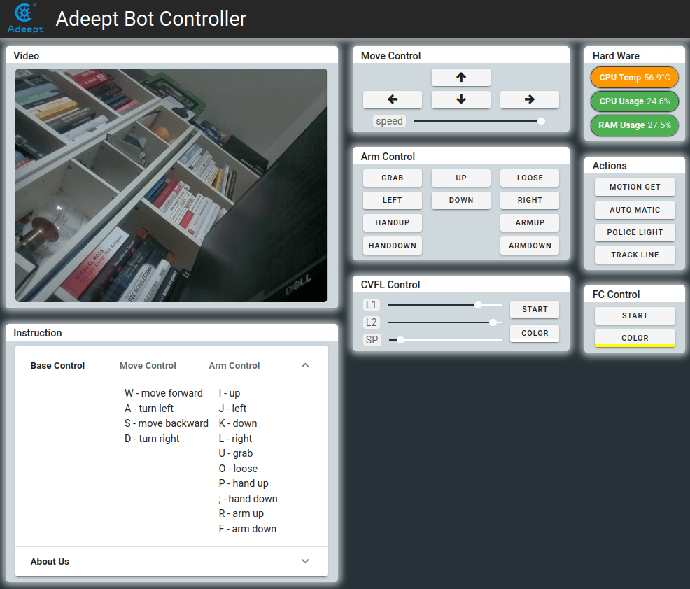
Finally I can run the web GUI. It looks like this:
Conclusion
This article details how to setup the Raspberry Pi Tank on an Raspberry Pi with Ubuntu Server 20.04. To make the kit work, requires libraries need to be changed, the I2C initialization ensured, the GPIO communication enabled, and camera software installed. In addition, I also explained how to automatically start the service using a systemd unit file and the detailed process to get the Raspberry Pi camera working.