Raspberry Pico: Drawing Sprite Animations with Circuit Python
—
The Raspberry Pico is a unique microcontroller. Its multi-faceted GPIO pins can be programmed for different purposes, and multiple SPI and I2C bus systems exists. A recent use case that I'm investigating is the ability to draw sprites, a sequence of images shown with short interim delays that give the impression of an animation. The popularity of the Pico microcontroller paired with the availability of several hardware components creates multiple solution options.
In my last article, I considered and explored MicroPython in general, and the Pimoroni-Pico MicroPython firmware specifically. This article is all about CircuitPython and specific display drivers created by Adafruit. It explores the libraries to control displays and draws graphics, with the goal to draw sprites on an n ST7565 display. This article is published although I could not fulfill this goal, yet I hope that others take the presented ideas when working on similar projects.
The technical context for this article is CircuitPython v9.2.1 and Adafruit_CircuitPython_ST7565 1.1.10. Code examples shown in this article should work with newer versions as well.
Requirements
For the context of this article, you need the following hardware:
- Raspberry Pico / Raspberry Pico W
- An ST7565 display (my concrete variant is the Pico GFX Pack)
Note: The display is distributed as two different versions, ST7565 and ST7567. I could not discern any hardware differences, and therefore, you can use libraries interchangeable.
Setup
The first step is to install the correct firmware for your Pico.
- Download CircuitPython for your board, either the Pico or the PicoW
- Reconnect the Pico to your computer while holding the bootsel button
- Drag and drop the firmware to the mounted USB drive
The Pico will reboot, and then reconnect as a USB drive with the device name CIRCUITPYTHON. If you do not see this name, then you should completely erase the flash drive too. Its the same procedure as above, but you will use the firmware flash_nuke2 - also see the description Flash Resetting UF2.
DisplayIO Library
I decided to start with the most enhanced and most recent CircuitPython library for accessing any kind of displays: The aptly named DisplayIO. This library provides both sophisticated abstractions for rich GUI design and a generic wrapper to access concrete displays. Before diving into the GUI design, the first step is to get the display running, to get it drawing anything.
Following the official documentation, you need to create a displayio object by passing in a connection protocol object, such as I2C or SPI (called FourWire in the library), and additionally a specific pin configuration for the target. The GfxPack hardware that is used for this project is a ST7565 display connected via SPI.
The template source code to establish the display connection is this:
display_bus = displayio.FourWire(
    board.SPI(),
    command=board.D10,
    chip_select=board.D9,
)
This code does not work out of the box - the pins for command and chip_select need to match the hardware. But more surprising was the fact that the method to access the SPI configuration of the Raspberry Pico does not work - because it is not defined at all.
Listening all objects of the board object, it is clear that almost only the pins are exposed:
dir(board)
# ['__class__', '__name__', 'A0', 'A1', 'A2', 'A3', 'GP0', 'GP1', 'GP10', 'GP11', 'GP12', 'GP13', 'GP14', 'GP15', 'GP16', 'GP17', 'GP18', 'GP19', 'GP2', 'GP20', 'GP21', 'GP22', 'GP23', 'GP24', 'GP25', 'GP26', 'GP26_A0', 'GP27', 'GP27_A1', 'GP28', 'GP28_A2', 'GP3', 'GP4', 'GP5', 'GP6', 'GP7', 'GP8', 'GP9', 'LED', 'SMPS_MODE', 'STEMMA_I2C', 'VBUS_SENSE', 'VOLTAGE_MONITOR', '__dict__', 'board_id']
From these names, only STEMMA_I2C is a function, and the others are only pin names. With this observation, I stopped exploring DisplayIO for the time being, and instead ventured into a hopefully directly working specific display driver.
ST7565 Library
The CircuitPython firmware is developed by Adafruit. It comes bundled with a wide range of libraries, supporting most products offered by the company. Yet, in contrast to the Pimoroni-Pico MicroPython fork, Adafruit also publishes additional libraries that can be installed.
The ST7565 library is dedicated to the very display that is used in the context of this article. Alas, a quick glance at the documentation reveals the need to setup the display with direct specification of an SPI bus and additional special pins:
display = adafruit_st7565.ST7565(spi, dc, cs, reset)
It seems like a "back to square one" situation, the concrete pin setup needs to be determined. But first the library needs to be installed.
Note: A general internet search also revealed the 9 year old library ST7565-LCD from Adafruit. Given its long dormancy, and the fact that it only supports C bindings, it is not further investigated in this article.
Library Installation
Specific CircuitPython libraries can be installed with the following steps.
- Download the latest library ZIP file from the Gitlab repository Adafruit_CircuitPython_Bundle
- On the Pico device, create the
libfolder - Identify the required libraries, and copy their
*.mpyfiles from the expanded ZIP file to the Pico with the same directory structure (which means flat files as is, and directories are copied recursively)
For a full explanation, see the CircuitPython Libraries documentation.
With the file(s) in place, run the following code to test it:
import adafruit_st7565

dir(adafruit_st7565)
#['__class__', '__name__', 'const', '__dict__', '__file__', '__version__', 'spi_device', 'time', 'framebuf', 'ST7565', '__repo__']
When no error occurs, we can continue.
Revere Engineering Pin Definition
Naturally, the display connection can only succeed when the correct pins are defined. An internet search for schematics yielded the GFX_pack_schematic.pdf - it shows the pins of the display and the Pico, but I was not used to reading these, and stayed confused about the concrete SPI interface and display reset pin. The only other option to get the concrete pins was to reverse engineer several source code files. Here is the complete journey.
The concrete ST7565 display is initialized as follows:
// source: pimoroni-pico/libraries/gfx_pack/README.md

#include "gfx_pack.hpp"
#include "drivers/st7567/st7576.hpp"
#include "libraries/pico_graphics/pico_graphics.hpp"
#include "rgbled.hpp"
#include "button.hpp"

// Display driver
ST7567 st7567(128, 64, GfxPack::gfx_pack_pins);
The constructor receives a width, height, and a set of pins. Heading over to the gfx_pack.hpp header file, the mentioned pins, and additionally all pins for onboard buttons and the background RGBW can be found.
// Source: https://github.com/pimoroni/pimoroni-pico/blob/main/libraries/gfx_pack/gfx_pack.hpp

static const SPIPins gfx_pack_pins = {PIMORONI_SPI_DEFAULT_INSTANCE, 17, SPI_DEFAULT_SCK, SPI_DEFAULT_MOSI, PIN_UNUSED, 20, 9};
    static const int WIDTH = 128;
    static const int HEIGHT = 64;
    static const uint8_t A = 12;
    static const uint8_t B = 13;
    static const uint8_t C = 14;
    static const uint8_t D = 15;
    static const uint8_t E = 22;
    static const uint8_t BL_R = 6;
    static const uint8_t BL_G = 7;
    static const uint8_t BL_B = 8;
    static const uint8_t BL_W = 9;
But what are the concrete pins of those constants? This is defined in pimoroni_common.hpp.
// source: https://github.com/pimoroni/pimoroni-pico/blob/main/common/pimoroni_common.hpp

#include <stdint.h>
#include <climits>
#include "pico/stdlib.h"

#define PIMORONI_I2C_DEFAULT_INSTANCE i2c0
#define PIMORONI_SPI_DEFAULT_INSTANCE spi0

// ....

static const unsigned int SPI_DEFAULT_MOSI = 19;
static const unsigned int SPI_DEFAULT_MISO = 16;
static const unsigned int SPI_DEFAULT_DC = 16;
static const unsigned int SPI_DEFAULT_SCK = 18;

static const unsigned int SPI_BG_FRONT_PWM = 20;
static const unsigned int SPI_BG_FRONT_CS = 17;

static const unsigned int SPI_BG_BACK_PWM = 21;
static const unsigned int SPI_BG_BACK_CS = 22;
With this, the concrete ST7565 display initialization becomes the following:
st7567(128, 64,
  {PIMORONI_SPI_DEFAULT_INSTANCE,
  17,
  18,
  19,
  PIN_UNUSED,
  20,
  9});
And finally, the role of each pin is revealed in the projects README.md ...
// source: pimoroni-pico/libraries/gfx_pack/README.md

ST7789 st7789(WIDTH, HEIGHT, ROTATE_0, false, {
    PIMORONI_SPI_DEFAULT_INSTANCE, // SPI instance
    SPI_BG_FRONT_CS,               // Chip-select
    SPI_DEFAULT_SCK,               // SPI Clock
    SPI_DEFAULT_MOSI,              // SPI Out
    PIN_UNUSED,                    // SPI In
    SPI_DEFAULT_DC,                // SPI Data/Command
    PIN_UNUSED                     // Backlight
});
... which provides this pin declaration:
PIMORONI_SPI_DEFAULT_INSTANCE = spi0  // SPI instance
SPI_BG_FRONT_CS = 17                  // Chip-select
SPI_DEFAULT_SCK = 18                  // SPI Clock
SPI_DEFAULT_MOSI = 19                 // SPI Out
PIN_UNUSED = PIN_UNUSED               // SPI In
SPI_DEFAULT_DC   = 20                 // SPI Data/Command
PIN_UNUSED       = 9
Display Connection & Drawing
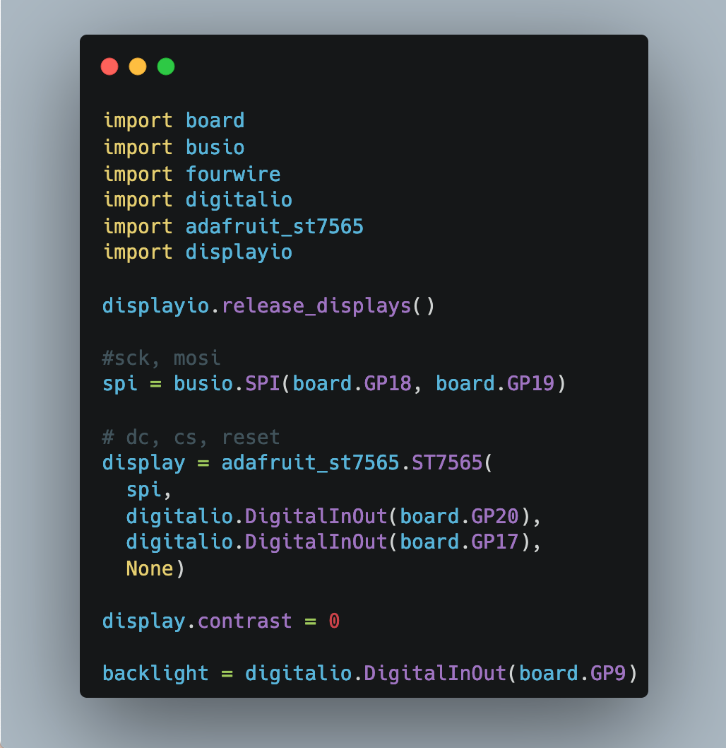
Based on the projects example, the following code connects to the display, flashes the backlights, draws a line and then fades the background.
from time import sleep
import board
import busio
import fourwire
import digitalio
import adafruit_st7565
import displayio

displayio.release_displays()

#sck, mosi
spi = busio.SPI(board.GP18, board.GP19)

# dc, cs, reset
display = adafruit_st7565.ST7565(spi, digitalio.DigitalInOut(board.GP20), digitalio.DigitalInOut(board.GP17), None)
display.contrast = 0

backlight = digitalio.DigitalInOut(board.GP9)
backlight.switch_to_output()

backlight.value = True
sleep(1)
backlight.value = False
sleep(1)
backlight.value = True
sleep(1)

display.fill(0)
display.line(0,63,127,0,1)
display.show()

while True:
    display.invert
    sleep(4)
    display.show()
Here is a screenshot of the result:
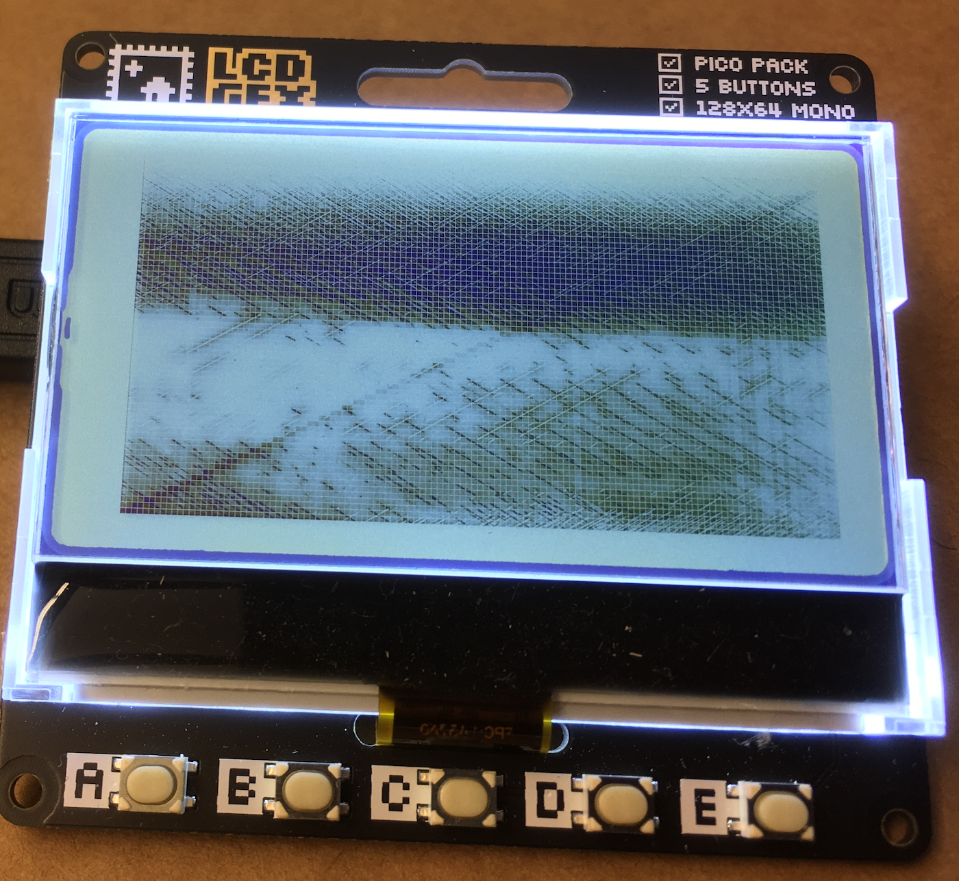
At this point, I could draw simple structures on the display. But what about sprites? What about picture formats? Unfortunately, there is no support. I doubt that I could port an image processing library to work with the ST7565 library. But understanding the display connection, lets use the DisplayIO library one more time.
DisplayIO Library (Retry)
The DisplayIO library has an extensive documentation titled display and display bus that details the connection setup. Alas, it has no direct support for an ST7565 display, and therefore, the display needs to be setup manually.
With the concrete pins of the GFX pack, the physical connection with an SPI connection takes the following form:
from time import sleep
import board
import busio
import fourwire
import digitalio
import adafruit_st7565
import displayio

displayio.release_displays()

#sck, mosi
spi = busio.SPI(board.GP18, board.GP19)

# dc, cs, reset
display_bus = displayio.FourWire(
    spi,
    command=board.GP20,
    chip_select=board.GP17,
)

print(dir(display_bus))
# ['__class__', 'send', 'reset']
Yet, to start using the display, it needs to be initialized with the following code stanza:
display = displayio.Display(
    display_bus,
    _INIT_SEQUENCE,
    width=128,
    height=64,
)
The documentation has a clear paragraph about this:
The init sequence (init_sequence) is a bit of a cryptic mess. We've worked it out for some displays and have created some light weight drivers that take care of the boiler plate.
But what is it? A set of commands issued from the microcontroller to read from, or write to, the display hardware registers so that it can be controlled with further command.
This sequence needs to be provided in a Python byte array. Here is an example for a similar board:
# Source: https://github.com/adafruit/Adafruit_CircuitPython_ST7789/blob/main/adafruit_st7789.py

_INIT_SEQUENCE = (
    b"\x01\x80\x96"  # _SWRESET and Delay 150ms
    b"\x11\x80\xFF"  # _SLPOUT and Delay 500ms
    b"\x3A\x81\x55\x0A"  # _COLMOD and Delay 10ms
    b"\x36\x01\x08"  # _MADCTL
    b"\x21\x80\x0A"  # _INVON Hack and Delay 10ms
    b"\x13\x80\x0A"  # _NORON and Delay 10ms
    b"\x36\x01\xC0"  # _MADCTL
    b"\x29\x80\xFF"  # _DISPON and Delay 500ms
)
Digging into the ST7565 library again, I could find that there is an init sequence too.
# Source: https://github.com/adafruit/Adafruit_CircuitPython_ST7565/blob/main/adafruit_st7565.py

# LCD bias select
self.write_cmd(self.CMD_SET_BIAS_7)
# ADC select
self.write_cmd(self.CMD_SET_ADC_REVERSE)
# SHL select
self.write_cmd(self.CMD_SET_COM_NORMAL)
# Initial display line
self.write_cmd(self.CMD_SET_DISP_START_LINE)
# Turn on voltage converter (VC=1, VR=0, VF=0)
self.write_cmd(self.CMD_SET_POWER_CONTROL | 0x4)
time.sleep(0.05)
# Turn on voltage regulator (VC=1, VR=1, VF=0)
self.write_cmd(self.CMD_SET_POWER_CONTROL | 0x6)
time.sleep(0.05)
# Turn on voltage follower (VC=1, VR=1, VF=1)
self.write_cmd(self.CMD_SET_POWER_CONTROL | 0x7)
time.sleep(0.01)
# Set lcd operating voltage (regulator resistor, ref voltage resistor)
self.write_cmd(self.CMD_SET_RESISTOR_RATIO | 0x7)
# Turn on display
self.write_cmd(self.CMD_DISPLAY_ON)
# Display all points
self.write_cmd(self.CMD_SET_ALLPTS_NORMAL)
Alas, I could not find any information how to translate these byte sequences and their timings into a working command. A plain translation of the commands yielded this:
_INIT_SEQUENCE = (
  b"xA3" # CMD_SET_BIAS_7)
  b"xA1" # CMD_SET_ADC_REVERSE)
  b"xC0" # CMD_SET_COM_NORMAL)
  b"x40" # CMD_SET_DISP_START_LINE)
  b"x28/x4" # CMD_SET_POWER_CONTROL | 0x4) | how to encode sleep 0.05?
  b"0x4/x6" # CMD_SET_POWER_CONTROL | 0x6) | how to encode sleep 0.05?
  b"0x4/x7" # CMD_SET_POWER_CONTROL | 0x7) | how to encode sleep 0.01?
  b"x20/x7" # CMD_SET_RESISTOR_RATIO | 0x7)
  b"xAF" # CMD_DISPLAY_ON)
  b"xA5" # CMD_SET_ALLPTS_NORMAL)
)
This sequence could by consumed by the board as shown:
# ...

display = displayio.Display(
    display_bus,
    _INIT_SEQUENCE,
    width=128,
    height=64,
)

print(dir(display))
# ['__class__', 'auto_refresh', 'brightness', 'bus', 'fill_row', 'height', 'refresh', 'root_group', 'rotation', 'show', 'width']
But the resulting display object could not be used - nothing was drawn in the display. And with this, I stopped the investigation of sprite drawing with CircuitPython completely.
Conclusion
This article explored two options to draw sprites on an LCD display with a CircuitPython context. The first option is to use the ST7565 library. It connects successfully to the display, can regulate the backlight, draw individual pixels - but it does not support image file processing. The second option is to use the modern displayIO library, which provides rich abstractions for complex screen designs and image file loading - but I could not get my display to work with it.
The long endeavour surfaced two learnings. First, display driver setup requires the correct protocol and pin declarations, which for a commercial product can be learned from schematics and source code reverse engineering. Second, display driver support is ultimately driven by products that sell well and receive support. For the ST7565 display used in this article, Adafruit discontinued its ST7565 Positive LCD several years ago, so there no support for it in the modern displayio library. Yet, a final hope prevails: To decipher and implement the display init sequence to get it working. This might be explored in a future article.