
The Tinker Board is a Single Board Computer from Asus. Its form factor, number of GPIO Pins, and general hardware capabilities resemble those of the Raspberry Pi. An important difference is the ARM Mali T764 GPU that contains Tensor Units tailored towards running Machine Learning applications.
This article details the Tinker Board hardware, its digital and analog pins, and the pin functions it offers.
Hardware
 Source: tinker-board.asus.com
The Tinker Board has the following components
- Processor: Quad-Core RK5288
- Graphics: ARM Mali T764
- SRAM: 2GB
- Clock Speed: 1800 MHz
- Digital GPIO: 26 pins, supporting up to 4xUART , 2xSPI, 2xI2C, 1xI2S
- Analog GPIO: 2 pins, supporting 2xPWM
There are several operating systems available for the Tinker Board S: The similarly named Tinker OS as well as other Debian and Ubuntu variants. Most can be downloaded from the manufacturer support page.
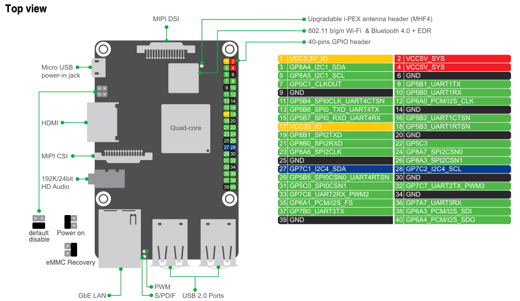
Digital Pins
 Source: tinker-board.asus.com
The digital GPIOs are labeled GP03-GP31 and GP34-GP40, with several GND and V Pins interspersed. Note that several pins can fulfill different roles, but that there is a limit to the amount of active protocols as specified above. Therefore, in programs you need to setup the pins accordingly.
To start programming on the Tinker Board with access to the pins, the manufacturer recommends to use prepacked API kits from their homepage. Supported programming languages are C and Python, and dependent on the OS installed, some pins are even accessible as Linux device files. Looking into the API kits, its apparent that the C version uses the Wiring Pi library, and the Python version uses RPI.
In the following section, I will give a brief example in Python and in C for each of the features.
Digital Output
Any pin can be set to serve as an output pin, and then you set the signal to low or to high. Code examples are as follows:
Python
import RPi.GPIO as GPIO

GPIO.setup(3, GPIO.OUT)
GPIO.output(3, GPIO.HIGH)
sleep(500)
GPIO.output(3, GPIO.LOW)
C
#include <wiringPi.h>

pinMode (3, OUTPUT);

digitalWrite (3, HIGH);
delay (500);
digitalWrite (3, LOW);
Analog Pins
The pins GP31 and GP32 can be used to read and generate PWM signals.
Analog Input
Python
import RPi.GPIO as GPIO

GPIO.setup(3, GPIO.IN, pull_up_down=GPIO.PUD_DOWN)
pwm_value = GPIO.input(3)
C
#include <wiringPi.h>

wiringPiSetupGpio();

pinMode (3, INPUT);
pwm_value = analogRead(3)
Analog Output
Comparable to other Single Board Computers and Micro Controllers, you are generating PWMs by setting the Pin and the max duty cycles, then start the PWM by setting a value smaller than the desired output. With the Python library, and software-based PWM can be generated, so you can also use any Pin for it.
Python
import ASUS.GPIO as GPIO
GPIO.setmode(GPIO.ASUS)

while True:
 GPIO.setup(16, GPIO.OUT)
 pwm = GPIO.PWM(16, 100)
 pwm.start(50)
C
#include <wiringPi.h>

wiringPiSetupGpio();
pinMode(3, PWM_OUTPUT) ;

//range=1s, period=0.5s, freq=1hz, val=0.5
asus_pwm_start(3,0,74250000,37125000);
GPIO Functions
On the TinkerBoard, you can use the following protocols when connecting with the right pins.
- UART: With the serial protocol, two devices can be connected directly for exchanging data.
- SPI: This protocol enhances the transportation capabilities of structured data by enabling a full-duplex connection in which one server can connect to multiple clients.
- I2C: Finally with this protocol, synchronous communication between multiple server and multiple clients becomes possible.
- PWM: To generate an analog signal, define a frequency and determine how often the signal changes between a high and low state.
- I2S: A serial bus interface to connect multiple audio devices and exchange PCM data.
Conclusion
The Tinker Board is a small-form factor Single Board Computer. It features a Quad-Core RK5288 CPU and ARM Mali T764 GPU suitable to run machine learning program. This brief article introduced the general hardware specification, pin layout, and pin function. Also, code examples to work with the digital and analog pins were shown.