My IOT@Home stack is based on ESP8266 boards, ESPHome, Home Assistant, and InfluxDB. Each component has a dedicated role: ESPHome is the tool to configure and manage the boards and their sensors, Home Assistant integrates all boards, provides dashboards for their data and automation options, and finally InfluxDB is for long-term data retention. During trying new sensors, a limit to the sensor network became apparent: Sensors can only be added if they are within Wi-Fi range.
Working on this limit, I tried first to build a custom external sensor that uses radio frequency to transmit data, and also investigated the OpenMQTT Gateway project. With this project, external sensors that transmit data via radio frequency, bluetooth, infrared, and even LoRa and GSM, can be integrated into an Iot@Home stack. The central data transmission and configuration mechanism is the name providing MQTT. After a quick period of trying this project for capturing my long-range radio frequency messages, I decide to give it a full try, to investigate and use it more thoroughly.
The technical context of this article is OpenMQTT Gateway v1.7.0 and an ESP32 board with RF receiver, in my case a LilyGo Lora T3. The examples should work with newer versions of the software and other supported boards as well.
Introduction to OpenMQTT
OpenMQTT is a true “standing on the shoulder of giants” project with a dedicated and strong developer community. The features and level of sophistication of this project is fantastic, I strongly advise you to take some time and browse the GitHub software repository.
In essence, OpenMQTT integrates dozen sensor reading libraries and communication libraries, ads MQTT message generation and configuration, Wi-Fi access and a WebUI. All of this is compiled to binaries that support more than 58 different boards, among them esp32, esp8266, and even some Arduino devices. See the complete supported board list, and given from this description, I could even use a standard esp32-ble-dev binary successfully for a board that is not listed there. Therefore, compatibility is even greater than anticipated.
What makes OpenMQTT outstanding for IOT projects is its support for a vast amount of end-consumer sensor products: indoor temperature and motion sensors, power switches and relays, smart meter, outdoor weather stations, and Bluetooth smart watches. There is a full list of supported sensor products, and I’m sure you will find things that you did not yet know about!
The final aspect that make OpenMQTT so convincing is its easy setup. In your home infrastructure, you just need an MQTT broker. That is all! To add a gateway board, you can just install the precompiled binaries via your browser. You do not need to have an additional program to flash your devices, and you don’t need a configuration tool either. Once flashed, the device opens a local hotspot. Connect to it, then add the credentials to your Wi-Fi and MQTT broker, and restart the device. A short amount of time later you will see the first OpenMQTT messages from detected sensors arriving.
Now, lets substantiate this introduction and build an OpenMQTT RF gateway.
Required Hardware
At the time of writing, the OpenMQTT homepage lists following microcontroller boards as being supported: esp32dev, esp8285, and nodemcuv2. But what is the difference between several types of prebuild binaries for each of these boards?
The answer lies with OpenMQTT creators’ inquisitive nature. For example, he wrote this blog post about hacking and flashing an USB stick that includes RF antenna. In this post, a consumer product was turned into a RF gateway. This product includes a specific type of RF chipset, and therefore needs a specific library to operate.
Scale the experience of 5 years consumer product hacking, and the big table of supported boards start to make sense: The description and the included libraries column detail which specific libraries are supported. And they in turn support different hardware that is included on the consumer products.
To sum up this excurse, you have two options to setup an OpenMQTT gateway: Choose a supported consumer product, or consult the projects documentation for the gateway protocol, e.g. RF hardware and libraries, to determine required boards and hardware that you need to solder.
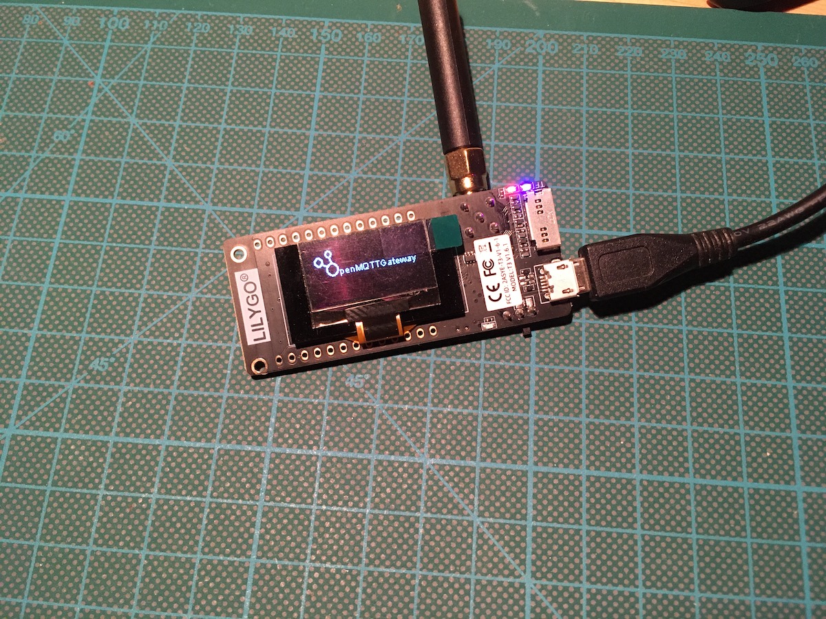
When you come from ESPHome background where you are used to combine boards and sensors that are supported, the idea of using a consumer product and flashing seems strange. But it makes sense and essentially is more convenient for a wider audience. And therefore, I went the coinvent way as well and bought a LilyGo Lora T3 v1.61 board. This board is based on an ESP32 chip, has an RF433 MhZ antenna and an onboard LED. It looks like this:

The next step is the initial flashing.
Initial Flashing
Flashing the device with one of the prebuilt binaries requires you to have the Chrome browser. Then, follow these steps:
- Connect the Lilygo board via USB to your computer
- Browse to the web install board selection page
- In the checkbox, select the board
lilygo-rtl_433 - A system dialogue opens, asking you to confirm that your device can be flashed (the device path will be OS specific, on Max OsX, my path was
/dev/cu.wchusbserial1410) - Th flashing process begins
If all went well, the device will restart and display the OpenMQTT Gateway logo.
Configuring Wi-Fi and MQTT Credentials
In its initial state, no configuration details are provided. The device will open a local Wi-Fi hotspot with the name OMG_lilygo_rtl_433_esp. Open it with your browser or mobile phone, and you will see the following WebUI:
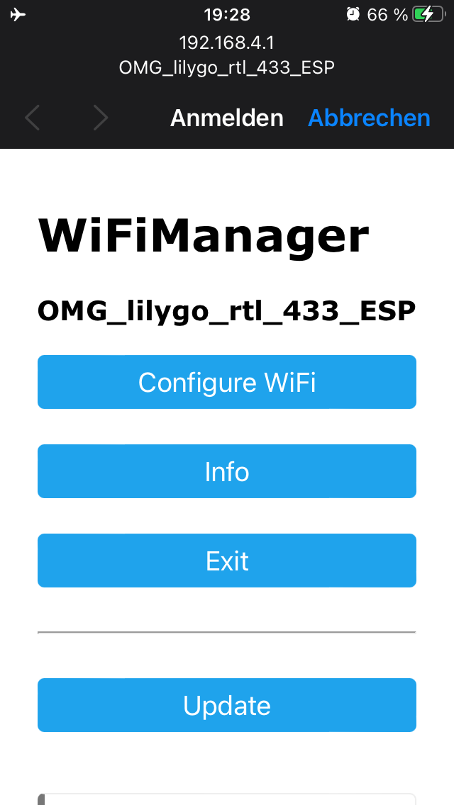
Here, click on Configure Wifi and enter your Wi-Fi credentials as well as the connection details to your MQTT broker. Then, click “Save” and click on “Exit” on the main screen.
After another reboot, the device will start to listen for any RF 433 Mhz signals and publish the results as MQTT messages.
Receiving MQTT Messages
Immediately after booting, following messages can be seen:
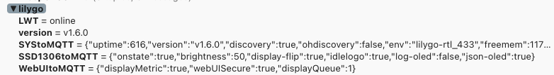
And in text form, the first topic are generic system stats of the board:
// lilygo/SYStoMQTT
{
  "uptime": 736,
  "version": "v1.6.0",
  "discovery": true,
  "ohdiscovery": false,
  "env": "lilygo-rtl_433",
  "freemem": 117064,
  "mqttport": "1883",
  "mqttsecure": true,
  "minfreemem": 95492,
  "tempc": 59.44444,
  "freestack": 5980,
  "rssi": -49,
  "SSID": "SECRET",
  "BSSID": "98:48:27:DB:6A:08",
  "ip": "SECRET",
  "mac": "SECRET",
  "actRec": 3,
  "mhz": 433.92,
  "RTLRssiThresh": -82,
  "RTLRssi": -94,
  "RTLAVGRssi": -91,
  "RTLCnt": 40,
  "RTLOOKThresh": 15,
  "modules": [
    "LilyGo_SSD1306",
    "WebUI",
    "rtl_433"
  ]
}
And two more topics that expose configuration options of the built-in LCD display and the web UI.
// lilygo/SSD1306toMQTT
{
  "onstate": true,
  "brightness": 50,
  "display-flip": true,
  "idlelogo": true,
  "log-oled": false,
  "json-oled": true
}

// lilygo/WebUItoMQTT
{
  "displayMetric": true,
  "webUISecure": true,
  "displayQueue": 1
}
Receiving External Sensor Data
Several years ago, I bought a generic indoor/outdoor temperature sensor. It consists of an external base station, operating outside, and a receiver with a display. Both sensors contain a temperature and humidity measuring sensor.
After some minutes, I was delighted to see the following message popping up via MQTT:
{
  "rssi": -94,
  "brand": "BALDR",
  "model": "B0134",
  "temperature": 21.32,
  "humidity": 61.30,
  "pressure": 1000.76
}
Just like that, the gateway received and interpreted the data of this particular sensor. And that is the comfort of the OpenMQTT Gateway: After its initial flashing and configuration, you will automatically pickup data from supported sensors, there is no more need to manually flash external sensors and/or hack their protocols. And not to be unmentioned: It will detect any signal within reach, and if you are living in a dense, urban neighborhood, you will pick up their sensor information as well.
Conclusion
OpenMQTT Gateway is an ideal starter project for IOT enthusiasts. This article showed you the minimal steps that are required to create a working RF 433 Mhz gateway: a) Choose a compatible ESP board that has all the required hardware, b) connect the device to your computer, c) from the OpenMQTT homepage, select the provided pre-compiled binary and flash the device directly from the browser, d) after a reboot, open the devices Wi-Fi hotspot, enter your Wi-Fi credentials and MQTT broker information. From thereon, you will receive MQTT message from all supported sensor in you vicinity. This is just the starting point of using OpenMQTT Gateway. In addition to RF 433 Mhz, it also supports Bluetooth, infrared, and even LoRa and GSM. And you can not only receive data, but also send commands to the devices. This will be explored in future articles.