For data transmissions, IOT devices typically use protocols like Wi-Fi or Bluetooth. But if the range increases, or when living in a dense urban area with many overlapping wireless networks, other techniques are required.
To extend the sensors range available to my Home Assistant installation, I decided to a use radio frequency-based connection. From the available transmission boards, I choose the NRF24L01: It operates in the 2.4GHZ spectrum and can transmit data as far as 1000m.
This article concludes my previous blog posts about building a remote GPS and temperature sender. It contains three parts. First, instructions how to assemble sender/receiver boards and connect all sensors. Second, the programming side, including reliable message sending/receiving and its conversion to MQTT messages. Third, the final field operation of the sensor and the errors I encountered and solved.
The technical context of this article is PlatformIO v3.3.1, Rf24 v1.4.8, and an esp8266 board. It should work with newer software versions as well as other boards that are supported by PlatformIO, such as an esp32.
Hardware Overview: Remote Sensor
For the sender, the following hardware is used:
- ESP8266 board
- NRF24L01
- NMEA GPS Sensor
- DHT11 Temperature Sensor
For the temperature sensor, I wanted to use the BM680, which provides atmospheric pressure as well as air quality measurements. However, I stuck an essential limitation: number of available pins. With the NRF antennas SPI Connection (5 digital pins), the GPS Sensor (2 digital pins), the temperature sensor (2 digital pins) and using D0 for deep sleep awakening, I was one pin short.
First, I tried to connect the GPS module with non-digital pins. But declaring AO as digital, or using the hardware TX and RX pin instead of the SoftwareSerial abstraction that all example library codes used, failed.
Second, with the NRF antenna, I tried to use A0 as a digital pin, e.g. the CSN or CN pin, but transmissions only worked when the board switched on - after exiting deep sleep, no transmissions were received. Spending something like 10 hours, I gave up and used a simpler DHT11 sensor which only needs 1 pin.
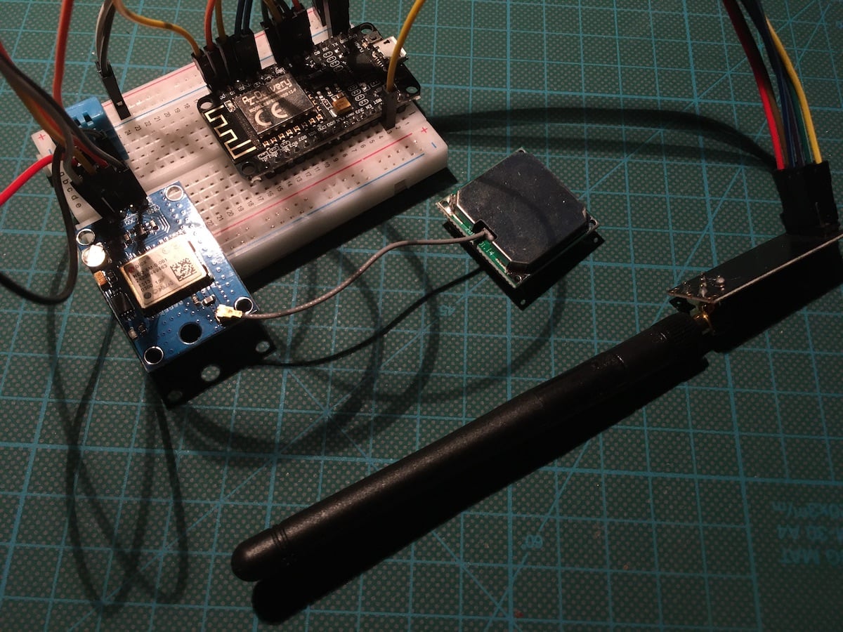
The completely connected board looks like this:

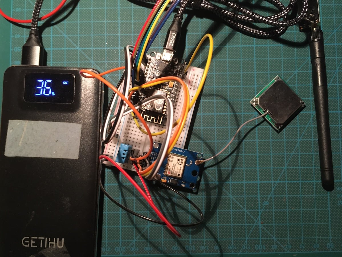
Another important aspect is the battery support. In the past time, I have been using a single 18650 Li-Ion Battery connected to a Wemos via a battery shield. For this project, I wanted a more long lasting, higher capacity solution because the GPS sensor certainly consumes much power. My solution is a power bank, an older model from 2018, which does not switch off when the power consumption falls during deep sleep phases.
The final sensor arrangement is this:
Hardware Overview: Receiver
The receiver is a much simpler project consisting of only two parts:
- ESP8266 board
- NRF24L01
Since I keep the sensor at my apartment, its powered via mains. Its assembly looks as follows:
Troubleshooting Message Passing
I spend several hours to solve various small problems in message passing between sender and receiver. Here are the most important ones to help you in case of similar problems too.
Note: The content of this section shows the earlier version of the sender in which a BME680 temperature sensor was used. Although I switched to a DHT11 sensor as explained above, these error are exemplarily of message passing.
Stacked Up Messages
The second error was that two measurements, the values for the pressure and humidity, were received as one message:
ALT=79.48
GAS=18.10
PRES=1003.73HUM=48.33
TEMP=26.59
My first attempt was to add an explicit delay(200) to the sender after each message transmission - the sender was receiving the data now correctly.
The solution: After fixing the payload size to 32 bytes, this error disappeared too. I can only assume its origin: Both messages were read into the same dynamic payload sized receive buffer.
Garbled Messages
The second error was garbled transmission data for the GPS location and date. It showed on the receiver as this:
DATE=2024-1000000000000000000000 ��?/
LOC=52.5060999999999999999999999 ��?/
What is the cause? Using dynamic payloads, I would expect the sender to fill up to 32 bytes if the message is longer. To debug this, I added a statement in the sender code to print the number of bytes. And it showed this:
DATE=2000-0-00-00:00:00 => 12 bytes
ALT=79.48 => 12 bytes
GAS=18.10 => 12 bytes
Quite unexpected! The message contains only a part of the complete DATE message. The solution: Set the payload explicitly to 32 bytes on the sender and receiver.
radio.enableDynamicAck();
radio.setPayloadSize(32);
And then it worked:
DATE=2023-10-29-12:15:23
LOC=52.50609, ...
MQTT Connection and Message Parsing
For The MQTT connection, the PubSub Client library is used. Although it has not seen a new release since 2020, it’s the most often used library and provides all the features required for this task.
To use the MQTT library, you define a PubSubClient object as shown:
WiFiClient wifiClient;

// mqtt
IPAddress mqtt_server(192, 168, 2, 200);
const int mqtt_port = 1883;
const char *mqtt_client_id = "esp8266-rf24";
const char *mqtt_topic = "nodes/esp8266-rf24";

void callback(char *topic, byte *payload, unsigned int length)
{
  // handle message arrived
}

PubSubClient mqttClient(mqtt_server, mqtt_port, callback, wifiClient);
And in the setup as well as in the loop method, the MQTT connection is (periodically) renewed.
mqttClient.connect(mqtt_client_id);

  while (!mqttClient.connected())
  {
    delay(500);
    Serial.print(".");
    if (millis() > mqtt_starttime + 5000)
    {
      Serial.println(F(""));
      Serial.println(F("ERROR: MQTT not connected"));
      Serial.print("Failed with state ");
      Serial.println(mqttClient.state());
      break;
    }
  }
  if (mqttClient.connected())
  {
    Serial.println("MQTT connected");
  }
With the client connected, messages are published with the same named method mqttClient.publish() to which you need C-stings, which are essentially char arrays. However, working with char arrays is not comfortable, so I switched to CPP strings. By using the substring method, an incoming message is divided in its name and value. The name becomes part of the MQTT topic to be published, and the value is the payload. The following method contains all necessary conversion and publishes any sensor message with MQTT.
void parse_and_publish(String msg)
{
  int divider = msg.indexOf('=');

  String baseTopic = "nodes/esp8266-rf24";
  String msgTopic = "/" + msg.substring(0, divider);
  String msgValue = msg.substring(divider + 1);

  String topic = baseTopic + msgTopic;
  topic.toLowerCase();

  mqttClient.publish(topic.c_str(), msgValue.c_str());
}
Sensor Operation Troubleshooting
With message passing and MQTT translation, the main functionality of the project is fulfilled. In continuing to setup the sender in a remote location, powered by an USB bank, and doing a deep sleep with periodic wakeups for power consumption, yet more errors were encountered.
Deep Sleep
An esp8266 board provides several types of deep sleep modes, which is extensively and helpfully explained in the blog post ESP8266 (ESP-12F) deep sleep and light sleep with Arduino. For the remote sensor to exhibit deep sleep capabilities and reliable wakeup, following changes were necessary:
- Provide a global variable for the deep sleep duration
- Provide a global variable for the maximum amount of wake time
- During the wake time, power up sensor, make measurements, and broadcast via the NRF antenna
- Immediately stop when either the GPS location has been measured and transmitted successfully, or when the wake time period is exhausted
The variables are defined as shown (take care: The deep sleep is given in micro seconds, that 1 million of a second):
uint32_t startTime;

// deep sleep
uint32_t sleepTimeMicroSeconds = 1800e6; // e6 1.000.000 / 60e6 = 1min
uint32_t maxWakeTimeMillieSecond = 60e3; // e3 1000 / 60e3 = 1min
In the programs main loop, the conditional checks are these:
void loop()
{
  Serial.println(" : Start reading sensor data");

  gpsReadDelay(5000);
  sendGPS();
  // …

  Serial.println(" : Stop reading sensor data");

  if (gpsLocationSuccessfull or (startTime + maxWakeTimeMillieSecond < millis()))
  {
    String msg = "sleep=" + String(millis());
    Serial.println(msg);
    radio.write(msg.c_str(), sizeof(msg));

    ESP.deepSleep(sleepTimeMicroSeconds);
  }
}
And finally: Don’t forget to connect the D0 and the RST pins, or the deep sleep phase will never end!
Receiver Stopped Working
Having almost finished the sensor, a new unexpected bug showed up: The receiver reported to not receive messages any more. To find the error, I tried this:
- Use older versions of the receiver/sender software
- Change the NRF antenna of the sender
- Change the NRF antenna of the receiver
- Change the receiver board
You see the strategy: Verify working hardware, then check the software. A particular aspect eluded me all this time: The sender happily reports to send data even if no receiver is present! The radio.write() method actually returns a boolean value whether sending was successful.
Changing the code to use and report this boolean value …
String msg = "TEMP=" + String(bme.temperature);
Serial.println(msg);
success = radio.write(msg.c_str(), 32);

if (success)
{
  Serial.println("success");
}
else
{
  Serial.println("fail");
}
.. the senders output log showed:
TEMP=27.46
fail
And this led me to the true error: The NRF antennas chip select pin was not working! At this time of the project development, I was still using the BME sensor, and my NRF24L antenna code used the analog pin for CSN. This was a very costly error that took more than 6 hours to fix. For proper usage of the NRF library, always use proper digital pins.
Fixing GPS Positions
The GPS sensor turned out to be fiddly: After about a week of not using it, it took almost an hour again before the sender got a GPS signal fix. This challenge is especially crucial when the sender should be sleeping for a time period like 1 hour, then wake up and send its GPS coordinates. I solved this with a pure manual approach:
- Increase the ceramic antennas reception by adding a tin foil underneath it (see this trick on youtube).
- Assemble the remote sensor only immediate after a GPS signal could be fixed
The tin foil was especially effective. In a dry run, it reduced getting the GPS location from 1h to a mere 10 minutes.
Then, for the final assembly, I flashed the ESP board with a program without deep sleep instructions, waiting for the GPS signal fix. Once its available, I immediately flashed the sensor again with the original program, assembled all components in a box, and took the sensor operational.
Here are logging statements from the sender:
Check NRF24L radio
SPI Speedz      = 10 Mhz
STATUS          = 0x0e RX_DR=0 TX_DS=0 MAX_RT=0 RX_P_NO=7 TX_FULL=0
RX_ADDR_P0-1    = 0x0100000000 0xc2c2c2c2c2
RX_ADDR_P2-5    = 0xc3 0xc4 0xc5 0xc6
TX_ADDR         = 0x0100000000
RX_PW_P0-6      = 0x20 0x20 0x20 0x20 0x20 0x20
EN_AA           = 0x3f
EN_RXADDR       = 0x03
RF_CH           = 0x2a
RF_SETUP        = 0x23
CONFIG          = 0x0e
DYNPD/FEATURE   = 0x00 0x01
Data Rate       = 250 KBPS
Model           = nRF24L01+
CRC Length      = 16 bits
PA Power        = PA_LOW
ARC             = 3
Check GPS sensor
GPS sensor ok
Check DHT sensor
DHT sensor: OK
DHT+GPS+NRF24L: Ready for operation
6203 : Start reading sensor data
LOC=52.506202,13.289183 => 12 bytes
GPS location transmitted
DATE=2024-10-29-11:41:32 => 12 bytes
GPS date transmitted
TEMP=25.57 => 12 bytes
HUM=57.72 => 12 bytes
DHT data transmitted
17365 : Stop reading sensor data
And the receiver shows:
Check NRF24L radio
SPI Speedz      = 10 Mhz
STATUS          = 0x0e RX_DR=0 TX_DS=0 MAX_RT=0 RX_P_NO=7 TX_FULL=0
RX_ADDR_P0-1    = 0x0100000000 0xc2c2c2c2c2
RX_ADDR_P2-5    = 0xc3 0xc4 0xc5 0xc6
TX_ADDR         = 0x0100000000
RX_PW_P0-6      = 0x20 0x20 0x20 0x20 0x20 0x20
EN_AA           = 0x3f
EN_RXADDR       = 0x03
RF_CH           = 0x2a
RF_SETUP        = 0x23
CONFIG          = 0x0e
DYNPD/FEATURE   = 0x00 0x01
Data Rate       = 250 KBPS
Model           = nRF24L01+
CRC Length      = 16 bits
PA Power        = PA_LOW
ARC             = 3
Check MQTT connection
MQTT connected
BME sensor: OK
NRF24L Receiver: Ready for operation
...
5005: no payload received
...
TEMP=25.57
HUM=57.72
Conclusion
Communication range for sensors is a barrier and limit to data availability. Having worked with Home Assistant and ESP Home, the effective range for all sensors is Wi-Fi coverage. In an urban area, signal congestions are likely to happen. To put it blunt: You cannot setup a sensor that’s 100m or more away from your apartment and expect a Wi-Fi signal to arrive. To overcome this challenge, radio frequency sensors can be used. This article showed how to use the NRF24 radio system that operates in the 2.4GHZ spectrum and can transmit data as far as 1000m. You learned how to assembly a sender that fetches temperature and GPS data, and the how to build and program the receiver, which reads incoming messages and transforms them to MQTT messages injected via Wi-Fi. Overall, this project took about 30h to complete. To the many challenges contributed unfamiliarity with the essential Arduino Library, assembly and powering with an USB power bank, ensure correct message sending, fault-tolerant deep-sleep, and finally getting a GPS signal fix. Having overcome all these challenges, the door to add arbitrary sensors for long range communication is opened.