For data transmissions, IOT devices typically use protocols like Wi-Fi or Bluetooth. But if the range increases or signals are congested in a dense urban area, other techniques are required.
To extend the sensors range available to my Home Assistant installation, I decided to a use radio frequency-based connection that sends data from around 100 to 200 meters. From the available transmission boards, I choose the NRF24L01: It operates in the 2.4GHz spectrum and can transmit data as far as 1000m.
This article explains how to connect an NRF24L01 radio frequency board to an esp8266, and how to exchange data between two boards that act as sender or receiver. It complements my last article in which a manually programmed GPS and temperature sensor was created. This data will now be transmitted via radio frequency.
The technical context of this article is PlatformIO v3.3.1, Rf24 v1.4.8, and an esp8266 board. It should work with newer software versions as well as other boards that are supported by PlatformIO, such as an esp32.
Hardware Overview
In this article, the following hardware is used:
- ESP8266 board
- NRF24L01
- Dupont cables
My esp8266 board of choice is the D1 Wemos mini. For the NRF24L01, I choose the version which comes with an external antenna. As before, I purchased all components from my favorite online shop, checking both the price tag and customer recommendations for concrete products.
Wiring
The D1 mini pin layout is as follows:
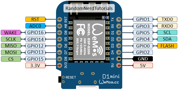
Source: randomnerdtutorials.com
The NRF24L01 must be connected via the SPI protocol. For the data transmission, 4+1 wires are required. First, the. SPI essentials: MISO, MOSI, SCLK, CS. Second, the NRFs CE pin, which means chip enabled, is an active high pin that set the NRF to either receive or send. The IRQ pin is optional and not required in this setup, it is used to send an interrupt to the SPI master to inform about new data being available.
Since the external antenna versions of the NRF24L do not have any pin labels, double check to get all of the following connections right:
- ESP8266 3.3V => RC522 VCC
- ESP8266 Ground => RC522 GND
- ESP8266 GPIO-14/D5 SCLK => RC522 SCLK
- ESP8266 GPIO-12/D6 MISO => RC522 MISO
- ESP8266 GPIO-13/D7 MOSI => RC522 MOSI
- ESP8266 GPIO-15/D8 CS => RC522 CSN
- ESP8266 GPIO-02/D4 => RC522 CE => RC522 IRQ
Also consult the following picture the connections details:
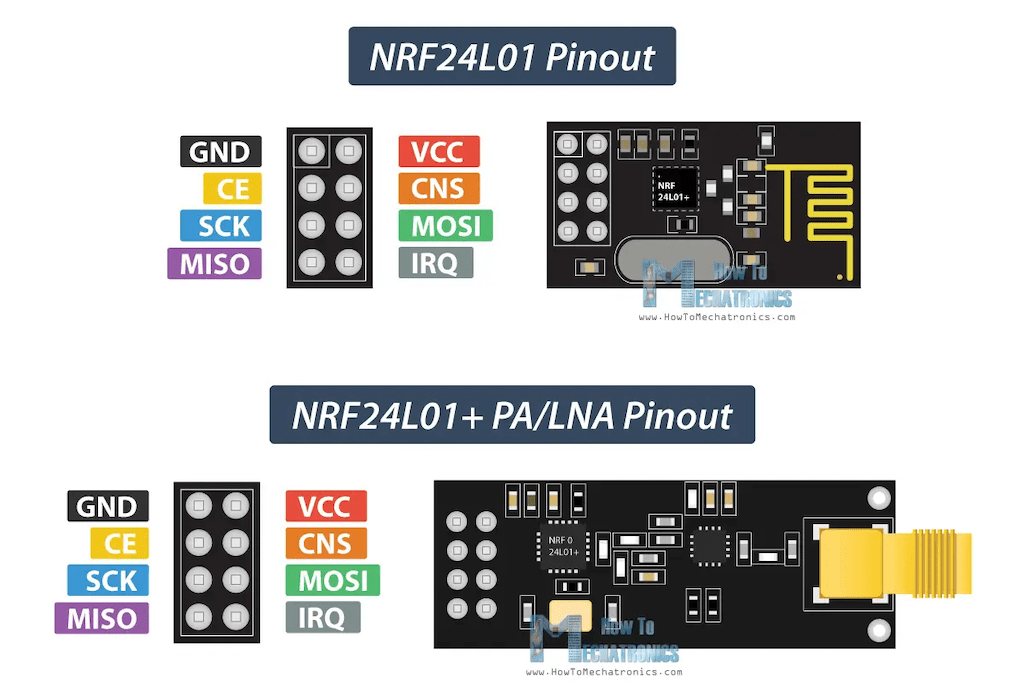
Source: howtomechatronics.com
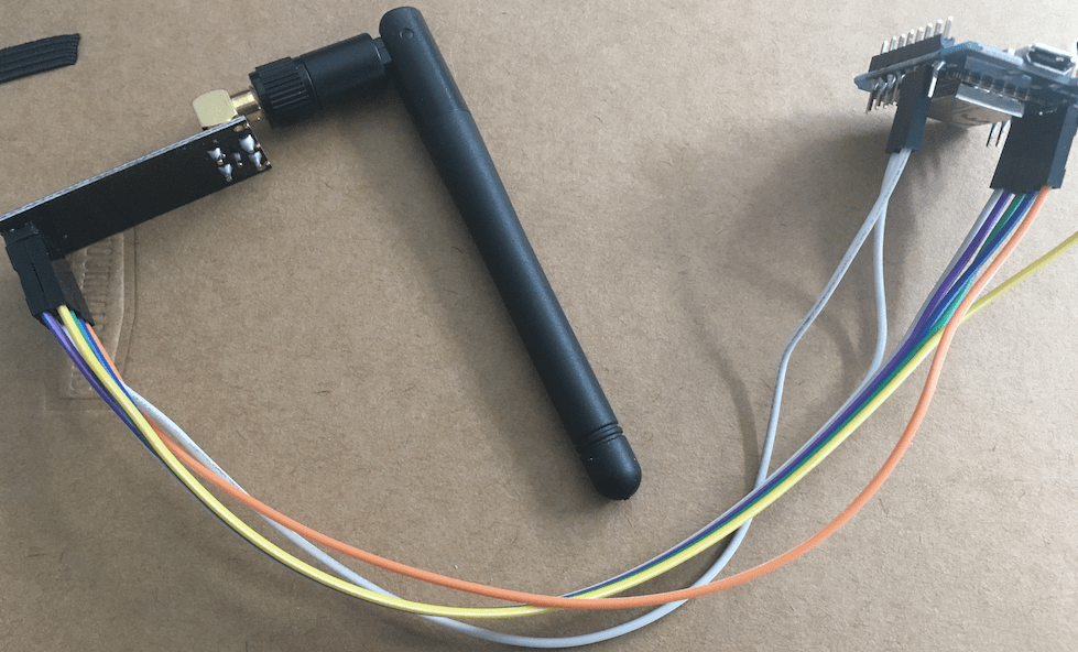
Having it all wired up, the board looks as follows:
Programming an NRF24 Sender – Basic Setup
Several libraries exist to use NRF sensors. After searching and reading usage examples and reports, I decided for the RF24 library. This library is in active development, and its GitHub project repo has many examples to get started. Using PlattformIO, the library was downloaded and automatically added to my project.
Alas, my start was rather rough: Using the scanner.ino example sketch to scan for radios, the ESP board only showed error messages, the program terminated immediately.
Soft WDT reset

Exception (4):
epc1=0x40002eee epc2=0x00000000 epc3=0x00000000 excvaddr=0x00000000 depc=0x00000000

>>>stack>>>

ctx: cont
sp: 3ffffe10 end: 3fffffd0 offset: 0160
3fffff70:  402016b0 3ffee588 3ffee5cc 402016a8
3fffff80:  402011a4 00000044 00000044 402011a9
3fffff90:  3ffee4da 0000004e 3ffee5cc 3ffee64c
3fffffa0:  40201f84 3ffe87e6 3ffee5cc 3ffee64c
3fffffb0:  3fffdad0 00000000 3ffee620 40202a30
3fffffc0:  feefeffe feefeffe 3fffdab0 40100d85

<<<stack<<<
In my next attempt, I tried the GettingStarted.ino sketch. This example looks intimidating because it contains the code for implementing both a transmitter and a receiver. Which role a flashed board takes is determined via an serial input at start up time. Digesting this unusual choice, I could get two devices talking to each other, but only with great care and double checking the wiring.
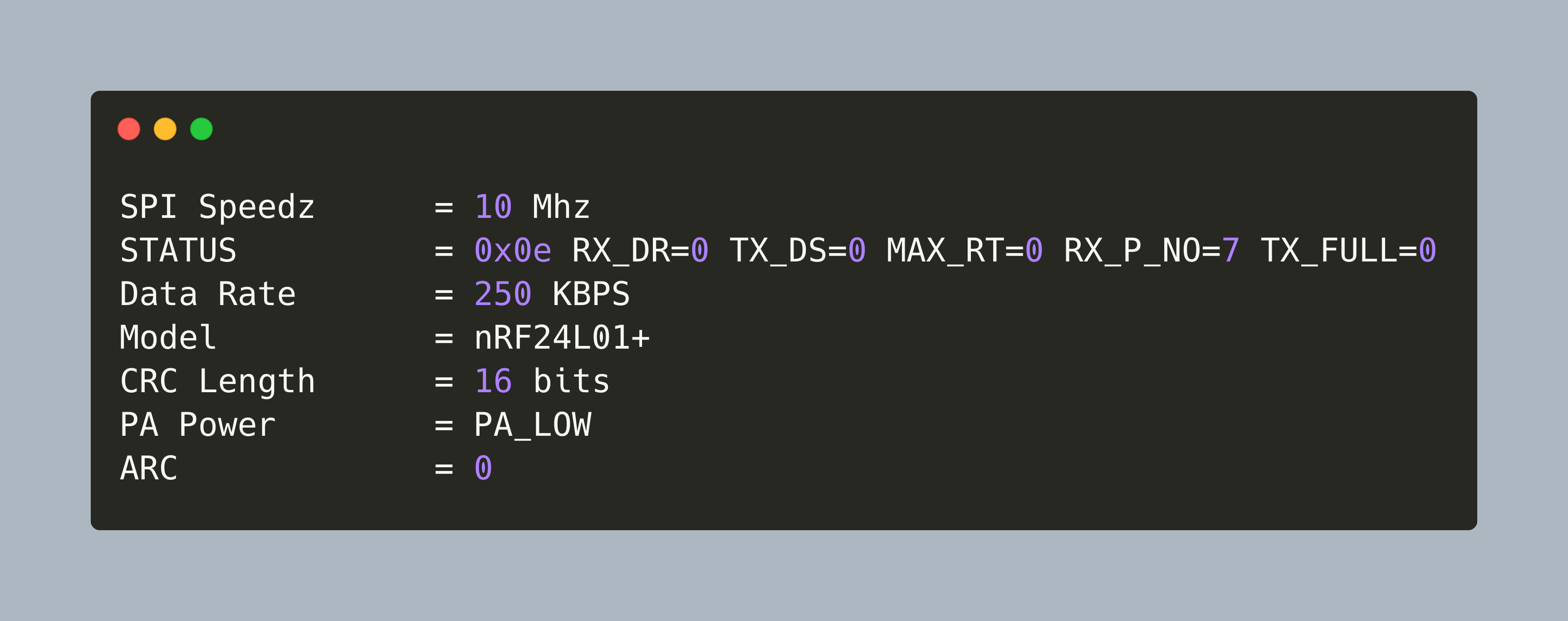
The most important hint from tje debug documentation is to use the command radio.printDetails(); and check that the output looks as follows:
SPI Speedz   = 10 Mhz
STATUS          = 0x0e RX_DR=0 TX_DS=0 MAX_RT=0 RX_P_NO=7 TX_FULL=0
RX_ADDR_P0-1    = 0xe7e7e7e7e7 0xc2c2c2c2c2
RX_ADDR_P2-5    = 0xc3 0xc4 0xc5 0xc6
TX_ADDR         = 0xe7e7e7e7e7
RX_PW_P0-6      = 0x20 0x20 0x20 0x20 0x20 0x20
EN_AA           = 0x00
EN_RXADDR       = 0x03
RF_CH           = 0x4c
RF_SETUP        = 0x27
CONFIG          = 0x0e
DYNPD/FEATURE   = 0x00 0x00
Also, print the configuration with radio.printPrettyDetails() and ensure that the values are equal for the sender and receiver.
Data Rate       = 250 KBPS
Model           = nRF24L01+
CRC Length      = 16 bits
PA Power        = PA_MAX
ARC             = 0
SPI Frequency           = 10 Mhz
Channel                 = 76 (~ 2476 MHz)
Model                   = nRF24L01+
RF Data Rate            = 250 KBPS
RF Power Amplifier      = PA_MAX
RF Low Noise Amplifier  = Enabled
CRC Length              = 16 bits
Address Length          = 5 bytes
Static Payload Length   = 32 bytes
Auto Retry Delay        = 1500 microseconds
Auto Retry Attempts     = 15 maximum
Packets lost on
    current channel     = 0
Retry attempts made for
    last transmission   = 0
Multicast               = Disabled
Custom ACK Payload      = Disabled
Dynamic Payloads        = Disabled
Auto Acknowledgment     = Disabled
Primary Mode            = TX
TX address              = 0xe7e7e7e7e7
pipe 0 ( open ) bound   = 0xe7e7e7e7e7
pipe 1 ( open ) bound   = 0xc2c2c2c2c2
pipe 2 (closed) bound   = 0xc3
pipe 3 (closed) bound   = 0xc4
pipe 4 (closed) bound   = 0xc5
pipe 5 (closed) bound   = 0xc6
Understanding the NRF24 Library
Since the examples are very concise and my start was rather rough, I took some time to read the API documentation and learn about available configuration options as well as which methods to use for sending and receiving data.
Configuration
The communication parameters are channels, payload size, acknowledgement, and crc codes. They can be set with the following:
RF24::enableDynamicPayloads()/RF24::disableDynamicPayloads()/RF24::setPayloadSize(): The payload, the length of a data transmission package, can have a fixed or dynamic size. If dynamic size is disabled, the payload size must be fixed.RF24::enableAckPayload()/RF24::disableAckPayload(): When using dynamic payloads, this allows to set auto acknoweledgement of - data transmissionsRF24::setCRCLength()/RF24::disableCRC(): Auto - acknowledgements requires CRC.
Therefore, you can configure data transmission with these features:
- fixed payloads
- fixed payloads + CRC
- fixed payloads + CRC + auto acknowledgement
- dynamic payloads
- dynamic payloads + CRC
- dynamic payloads + CRC + auto acknowledgement
There are also advanced configuration options:
RF24::setAddressWidth(): Set the address width from 3 to 5 bytes (24, 32 or 40 bit)RF24::setChannel(): Manually sets the channel for the transmission. The base is 2400Mhz, and the channel number is added to this:RF24::setDataRate(): The amount of data that can be transported. Smaller values can improve the reliability of the communication. Values are:RF24_2MBPS,RF24_1MBPSandRF24_250KBPS.setPALevel()- set the power consumption mode, values areRF24_PA_LOWandRF24_PA_MAX
Data Transmission
To start and use data transmissions, following methods are required
radio.begin(): Wakeup method for SPI communication with the radio module. Needs to complete before the radio module can be configured.radio.startListining()andradio.stopListening(): Nodes operate in sending or receiving mode. The default is receiving, and by callingstopListening()sending is activated. The role can be changed dynamically by using these methods.address- For the configured channel, device addresses need to be defined. These are 5 bytes. Since in C a string is represented as bytes, the example code uses byte strings such asuint8_t address[][6] = { "1Node", "2Node" }radio.openWritingPipe(address[radioNumber])- each node uses the default pipe0for writing dataradio.openReadingPipe(1, address[!radioNumber]);- the node can store received data in the other 5 pipesradio.available(&pipeNum): Checks if data is availbe in the specified piperadio.read(void * , uint8_t)reads that data from a pipe into a bufferradio.write(void * , uint8_t)sends a buffer to the radios writingPipeline
Programming the NRF24 Sender
With this understanding, dedicated sender and receiver code can be written.
Both the sender and the receiver share the following radioSetup() method:
void radioSetup()
{
  while (!Serial)
    {
    }

    Serial.println(F("Check NRF24L radio"));

    if (!radio.begin())
    {
      Serial.println(F("ERROR: NRF24L not responding"));
      while (1)
      {
      }
    }

  radio.setDataRate(RF24_250KBPS);
  radio.setChannel(42);
  radio.setPALevel(RF24_PA_LOW);

  radio.enableDynamicPayloads();
  radio.enableDynamicAck();

  radio.printDetails();
}
The sender uses radio.write() for transmitting data. Here is a small excerpt from sending temperature data:
void sendBME()
{
  bme.beginReading();
  delay(50);

  if (!bme.endReading()) {
    Serial.println(F("ERROR: BME reading failed"));
    return;
  }

  String msg = "TEMP " + String(bme.temperature);
  radio.write(msg.c_str(), sizeof(msg));
  // ...
}
The receivers continuously listen for new messages - if they arrive, they are printed immediately, and the reading buffer is reset.
void loop()
{
  uint8_t pipe;
  unsigned long start_timer = millis();
  if (radio.available(&pipe))
  {
    char buffer[32];
    radio.read(&buffer, sizeof(buffer));
    Serial.println(buffer);
  }
  else
  {
    if (start_timer + 10000 < millis())
    {
      start_timer = millis();
      Serial.print(millis());
      Serial.println(F(": no payload received"));
    }
  }
  delay(1);
}
During programming, I encountered the following challenges:
- Data size is 32 bytes: Only 32 bytes can be transmitted each time - this is far to less to transmit all data. In several forums, I saw solutions in which a C struct was created to hold several values, transmitted in multiple packets, then assembled and checked with manually created error codes. I took a simple approach: Each measurement is taken and transmitted immediately, and I don’t account for lost data, it doesn’t matter if a single temperature data drops once in a while.
- Buffer Size: The write buffer is finite. It’s possible to call
radio.write(), but this will corrupt memory eventually. Therefore, its best to program sender and receiver such that each send package is consumed as fast as possible so that the buffer is emptied and can be used again - Data format string vs. char array: The example code uses C
char[]and pointers. You can also use Arduino C++ strings, and then convert them tochar[]before sending:
  String msg = "TEMP " + String(bme.temperature);
  radio.write(msg.c_str(), sizeof(msg));
Transmitting GPS and Temperature Data
Finally let’s see example output of the program.
First, the radio connection details are printed. As mentioned above, be sure to compare them - they must be identical with each other.
Sender
SPI Speedz   = 10 Mhz
STATUS          = 0x0e RX_DR=0 TX_DS=0 MAX_RT=0 RX_P_NO=7 TX_FULL=0
RX_ADDR_P0-1    = 0x0100000000 0xc2c2c2c2c2
RX_ADDR_P2-5    = 0xc3 0xc4 0xc5 0xc6
TX_ADDR         = 0x0100000000
RX_PW_P0-6      = 0x20 0x20 0x20 0x20 0x20 0x20
EN_AA           = 0x3f
EN_RXADDR       = 0x03
RF_CH           = 0x2a
RF_SETUP        = 0x23
CONFIG          = 0x0e
DYNPD/FEATURE   = 0x3f 0x05
Data Rate       = 250 KBPS
Model           = nRF24L01+
CRC Length      = 16 bits
PA Power        = PA_LOW
ARC             = 0
The sender wakes periodically, then reads GPS and BME data:
621512 : Start reading sensor data
GPS data transmitted
BME data transmitted
622211 : Stop reading sensor data
And the receiver prints the concrete measurements:
LOC: 52.520645, 13.409779
DATE: 2023-10-07, 17:26:42:341
TEMP: 24.32
HUMI: 55.88
ALTI: 29.51
GAS: 120.31
Up to this point, all data is sent unencrypted. While the thought of somebody eavesdropping on temperature data is not a concern, broadcasting GPS signals is a different thing. I will explore this in a future article.
Conclusion
For long range data transmission, several options exist. This article investigated the NRF24L board which operates in the 2.4GHZ spectrum and can reach up to 1000m with an external antenna. You learned how to connect the NRF24L to an esp8266 via SPI, took an insight view into the NR24 library with its many configuration options, understood the essential API calls for transmitting and receiving messages, and saw an example in which GPS and temperature data are transmitted. With this, the remote sensor part is finished, and the next article investigates how the receiver transforms these messages into MQTT which are then consumed by Home Assistant.