In home automation systems, several sensors transmit and consume data, leading to automations that trigger behavior like turning on lights. One typical trigger of such automations is presence, the state of an entity being in a defined vicinity. And a very fine-tuned presence detection are GPS coordinates, enabling the declaration of an area surrounding your home, and in which vicinity presence is detected. Home Assistant and ESP Home are the essential cornerstones. Home Assistant can work with devices that transmit GPS coordinates: They are defined as an entity type called tags, and this can be used to define automations. Also, ESP Home can read and show GPS coordinates.
However, halfway through this project, I realized that ESP Home is still reliant in a strong Wi-Fi connection for transmitting data from sensor to the base station. So, a GPS sensor with some distance from my home will not work, especially in congested urban areas. What to do?
Long-range data transmission via radio frequencies has been tried and tested in several Arduino projects. It opens several options to extend available sensors too, and this idea got momentum: I wanted to build a remote GPS and temperature measuring sender that send data via radio frequency to a base station, and this base station converts the measurements to MQTT messages that are picked up by Home Assistant.
Therefore, the simple “read GPS coordinates with a configured ESP Home device” became a project with four steps: a) Build and program the GPS and temperature reader, b) add and program an radio-frequency sender, c) build and program the radio-frequency receiver that receives measurements and publishes them as MQTT, and d) setup Home Assistant integrations and automations.
This article is the first of three. It explores the GPS sensor component and programming. You will learn how to connect and ESP8266 board with an NMEA GPS sender and BME680 temperature sensor, see how to setup PlatformIO, learn which libraries to use, and see the final source code that reads temperature data and GPS coordinates.
The technical context of this article is PlatformIO v3.3.1, AdaFruit BME680 v2.0.2, TinyGPSPlus v1.0.3, and an esp8266 board. It should work with newer software versions as well as other boards that are supported by PlatformIO, such as esp32.
Hardware Overview
For this article, the following hardware is required:
- ESP8266 board
- BME680 temperature sensor
- NMEA-based GPS sensor
- Dupont cables
My esp8266 board of choice is the D1 Wemos mini, its compact and works for me very well. For the BME680 sensor, several vendors exist. For the GPS board, I choose one that supports the NMEA protocol (because it also has native support by ESP Home – according to this article the Neo-6M board works well with an esp8266.
Wiring
The D1 mini pin layout is as follows:
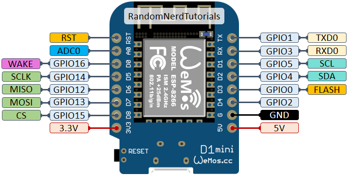
Source: https://randomnerdtutorials.com
The connection with the GPS board requires just two wires because the coordinates are communicated as simple UART messages. To read this serial data, any two digital pins can be used.
- ESP8266 3.3V => RC522 VCC
- ESP8266 Ground => RC522 GND
- ESP8266 GPIO-14 / TX => RC522 RX
- ESP8266 GPIO-12 / RX => RC522 TX
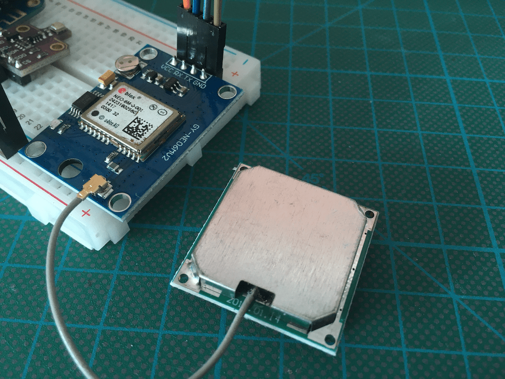
Connecting the GPS sensor looks like this:

The BME680 sensor can communicate via I2C and SPI. Since I2C requires less cables, I chose this method, which resulted in the following setup:
- ESP8266 3.3V => BME680 VCC
- ESP8266 Ground => BME680 GND
- ESP8266 GPIO-05 / SCL => BME680 SCL
- ESP8266 GPIO-04 / SDA => BME680 SDA
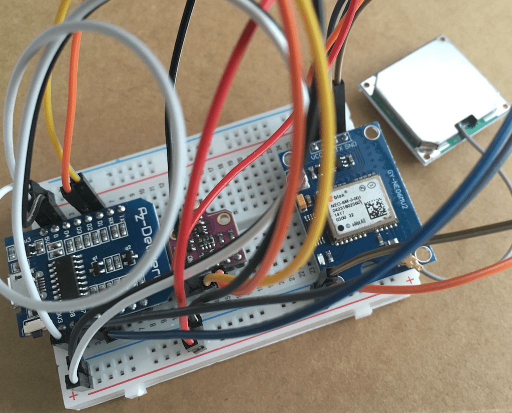
The final wiring, mounted in a breadboard, looks like this:
PlatformIO Project
PlatformIO is a versatile development environment that I used some time ago to setup a DHT temperature sensor. After this long time, I needed to re-learn how to use this IDE. The steps are:
- Install VS Code
- Add the PlatformIO Plugin
- Select the PlatformIO Plugin from the “icon bar” from the left side
- PlatformIO will download several additional libraries, once completed, VS code needs to be restarted
- From the “icon bar”, start the platform IO plugin
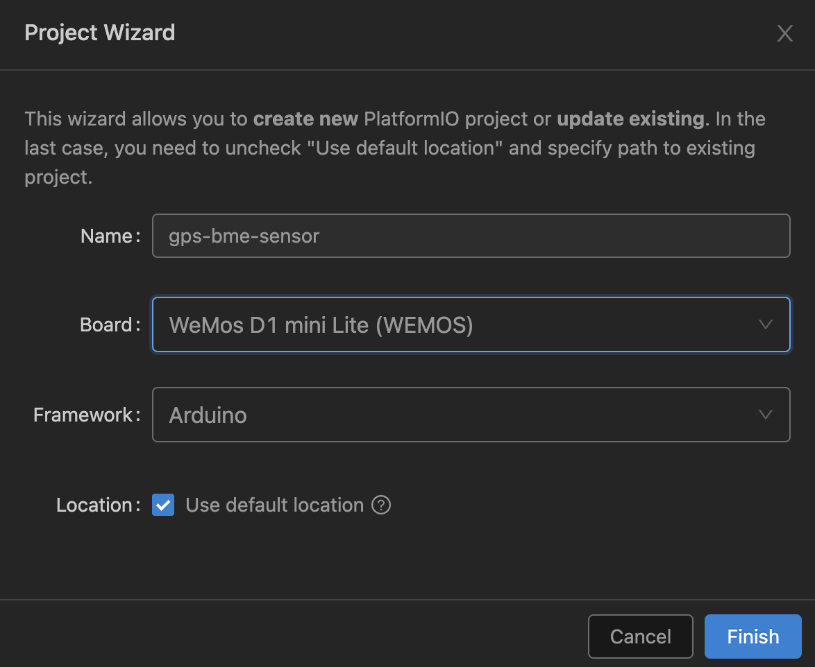
- Click on the “New Project” button, provide a name and the board, the project is created.
Let’s start with a simple program that prints “Hello World”.
#include <Arduino.h>

void setup() {
  Serial.begin(9600);
}

void loop() {
  Serial.println("Hello World!");
  delay(1000);
}
Then, Upload via the “arrow” icon.
CONFIGURATION: https://docs.platformio.org/page/boards/espressif8266/d1_mini_lite.html
PLATFORM: Espressif 8266 (4.2.1) > WeMos D1 mini Lite
HARDWARE: ESP8266 80MHz, 80KB RAM, 1MB Flash
PACKAGES:
 - framework-arduinoespressif8266 @ 3.30102.0 (3.1.2)
 - tool-esptool @ 1.413.0 (4.13)
 - tool-esptoolpy @ 1.30000.201119 (3.0.0)
 - tool-mklittlefs @ 1.203.210628 (2.3)
 - tool-mkspiffs @ 1.200.0 (2.0)
 - toolchain-xtensa @ 2.100300.220621 (10.3.0)
LDF: Library Dependency Finder -> https://bit.ly/configure-pio-ldf
LDF Modes: Finder ~ chain, Compatibility ~ soft
…
Building in release mode
…
RAM:   [===       ]  34.3% (used 28112 bytes from 81920 bytes)
Flash: [===       ]  27.7% (used 265591 bytes from 958448 bytes)
Configuring upload protocol...
AVAILABLE: espota, esptool
CURRENT: upload_protocol = esptool
Looking for upload port...
Auto-detected: /dev/cu.usbserial-14220
Connecting...
…
Chip is ESP8266EX
Features: WiFi
Crystal is 26MHz
…
Compressed 269744 bytes to 198422...
Writing at 0x00000000... (7 %)
Writing at 0x00004000... (15 %)
Writing at 0x00008000... (23 %)
… and it prints its message:
--- Terminal on /dev/cu.usbserial-14220 | 9600 8-N-1

Hello World!
Good. Now we can begin with the sensor code.
BM680 Temperature Sensor
PlatformIO provides great comfort to add libraries to a project. From the home screen, search for a library. Then, click on “Add to project” and select the appropriate project that you work on.
From the search results, I decided to use the Adafruit BME680 Library, which provides a base example that can be tried to get the sensor working. The libraries integration into a project is configured with the projects platformio.ini file:
[env:d1_mini_lite]
platform = espressif8266
board = d1_mini_lite
framework = arduino
lib_deps = adafruit/Adafruit BME680 Library@^2.0.2
Adding the example code to the main.cpp file, then clicking in the build icon (checkmark), the upload icon (vertical arrow), and finally connecting to the serial monitor icon (power plug), I could see these log messages:
Reading started at 11634 and will finish at 11815
You can do other work during BME680 measurement.
Reading completed at 11950
Temperature = 28.95 *C
Pressure = 1017.92 hPa
Humidity = 37.04 %
Gas = 4.16 KOhms
Approx. Altitude = -38.89 m
Yes! Let’s Continue with GPS.
GPS
For working with GPS, few things need to be considered:
- The connection to the GPS module needs to use software serial pins, not the built-in TX/RX pins, because these are used for the Serial-to-USB conversion that prints messages with PlatformIO’s serial monitor (see this forum.aduino.cc thread for a technical explanation).
- The raw GPS output data needs to be parsed to actual longitude and latitude coordinates - several libraries for this task exist.
Therefore, we need a combination of the built-in SoftwareSerial library and TinyGPSPlus.
The following sketch reads raw data:
#include <Arduino.h>
#include <SoftwareSerial.h>

SoftwareSerial software_serial(D6, D5);

void setup(){
  Serial.begin(9600);
  software_serial.begin(9600);
}

void loop(){
  while (software_serial.available() > 0){
    byte gpsData = software_serial.read();
    Serial.write(gpsData);
  }
}
The raw data looks as follows:
$GPGSV,4,3,13,20,16,197,23,22,53,150,15,23,10,328,12,24,07,258,*75
$GPGSV,4,4,13,30,49,074,29*4D
$GPGLL,ZZZ.37908,N,01317.35423,E,154704.00,A,A*6C
$GPRMC,ZZZZZZ.00,A,ZZZ.UUUU,N,01317.35454,E,0.237,,300923,,,A*7B
$GPVTG,,T,,M,0.237,N,0.439,K,A*2B
$GPGGA,ZZZZZZ.00,ZZZ.UUUU,N,01317.35454,E,1,06,2.59,40.4,M,42.3,M,,*67
$GPGSA,A,3,14,30,22,07,08,20,,,,,,,3.22,2.59,1.91*0D
I won’t dig into explaining this data format, because the library TinyGPSPlus parses it and provides latitude and longitude coordinates. From the projects GitHub page, I choose the DeviceExample.ino file as-is. This printed the following statements:
Location: 52.520645, 13.409779
Date/Time: 2023-10-03, 12:04:10:131
This looks good - coordinates and time are correct.
Integrated Temperature and GPS Sensor Readings
The final step is to write a program that periodically reads temperature and GPS data. In several example code, you will see the notation Serial.println(F("")), which puts string into flash memory. However, the program is compact as is, all strings can be stores in SRAM as well, which makes the print statements better readable.
Combining code blocks from above examples, I created the following:
#include <Arduino.h>

#include <Wire.h>
#include <SPI.h>
#include <Adafruit_Sensor.h>
#include <Adafruit_BME680.h>

#include <SoftwareSerial.h>
#include <TinyGPSPlus.h>

SoftwareSerial ss(D6, D5);
TinyGPSPlus gps;

#define SEALEVELPRESSURE_HPA (1013.25)

Adafruit_BME680 bme;

void setup(){
  Serial.begin(9600);
  ss.begin(9600);

  Serial.println(F("Check GPS sensor"));
  if (millis() > 5000 && gps.charsProcessed() < 10)
  {
    Serial.println(F("GPS sensor: ERROR"));
    Serial.println(F("No GPS detected: check wiring."));
    while(true);
  }
  else {
     Serial.println(F("GPS sensor: OK"));
  }

  Serial.println(F("Check BME sensor"));
  if (!bme.begin()) {
    Serial.println(F("BME sensor: ERROR"));
    Serial.println(F("Could not find a valid BME680 sensor, check wiring!"));
    while (1);
  }
  else {
    Serial.println(F("BME sensor: OK"));
  }

  // Set up oversampling and filter initialization
  bme.setTemperatureOversampling(BME680_OS_8X);
  bme.setHumidityOversampling(BME680_OS_2X);
  bme.setPressureOversampling(BME680_OS_4X);
  bme.setIIRFilterSize(BME680_FILTER_SIZE_3);
  bme.setGasHeater(320, 150); // 320*C for 150 ms
}

void printTemperatureData()
{
  bme.beginReading();
  delay(50);

  if (!bme.endReading()) {
    Serial.println(F("ERROR: BME reading failed"));
    return;
  }

  String msg = "TEMP " + String(bme.temperature);
  Serial.println(msg);

  msg = "PRES " + String(bme.pressure / 100.0, 2);
  Serial.println(msg);

  msg = "HUMI " + String(bme.humidity);
  Serial.println(msg);

  msg = "GAS " + String(bme.gas_resistance / 1000.0);
  Serial.println(msg);

  msg = "ALTI " + String(bme.readAltitude(SEALEVELPRESSURE_HPA));
  Serial.println(msg);
}

void printGpsData()
{
  if (!gps.location.isValid()) {
    Serial.println(F("ERROR: GPS location reading failed"));
  } else {
    String msg = "LOC";
    msg += String(gps.location.lat(), 6);
    msg += " ";
    msg += String(gps.location.lng(), 6);

    Serial.println(msg);
  }

  if (!gps.date.isValid() && !gps.time.isValid()) {
    Serial.println(F("ERROR: GPS date reading failed"));
  } else {
    String msg = "DATE";
    msg += gps.date.month() + "-";
    msg += gps.date.day() + "-";
    msg += gps.date.year() + " ";
    msg += gps.time.hour() +  ":";
    msg += gps.time.minute() +  ":";
    msg += gps.time.second() + ".";
    msg += gps.time.centisecond();

    Serial.println(msg);
  }
}

void loop()
{
  while (ss.available() > 0)
    if (gps.encode(ss.read())) {
      printGpsData();
      delay(2000);
      printTemperatureData();
      delay(2000);
    }
}
Conclusion
In my quest to build a remote temperature and GPS sensor, I realized that ESP Home requires a stable Wi-Fi connection for transmitting and receiving sensor data. Since long range Wi-Fi is not an option in a congested urban space, a new project started: The remote sensors connects to a base station via radio frequency, and this base state processes data and sends them via MQTT to my EspHome/Home Assistant stack.
This article lays the foundation: Manually programming an esp8266 sensor to read temperature and GPS data. You learned how to setup PlatformIO for manual programming, how to read GPS data from an NMEA sensor, and how to read temperature data from a BME680 sensor. The next article investigates the required hardware and libraries for a remote connection.