
My IOT enabled home grows sensor by sensor. In one of the last articles, I explained which new devices I want to integrate: Power switches and Wi-Fi lightbulbs. Starting with power switches, I made the experience of disassembling, soldering connection lines, and manual flashing. It required some dexterity to solder the connecting pins to the board, but it was possible. Then, manually flashing them with Tasmotizer, and they were available in my Home Assistant application.
Building on this positive surprise, I continued with the Wi-Fi Led Bulbs. I tried two methods. First, flashing the bulbs with a program called Tuya Convert, which essentially accesses the LEDs during pairing mode to upload a custom firmware. Second, disassembling the lightbulb, connecting wires to the internal board, and using a serial connection for flashing the device. Ultimately both approaches failed. This article explains my journey in the hope of helping other to approach this with different methods.
The technical context for this article is Tasmota 14.3, Tasmotizer #cc9d34e (2024-01-30), and ESPHome v2024.10.3. All given examples should work with newer versions of the firmware and library too.
Hardware
Checking the available Wi-Fi Led Bulbs on the official Tasmota device list, I found this entry for a Hama E27 10W RGBW Wi-Fi Bulb. According to the specs, it features a ESP8266 board that connects with SM16716 Addressable LED ring to create RGB colors.
First Try: Wi-Fi Flashing with Tuya Convert
Tuya Convert is a software that creates a local Wi-Fi hotspot that injects packages into a Wi-Fi Led bulb to install a custom firmware. To start with this process, you need a computer or laptop with a Debian based Linux distribution. A Raspberry Pi is good as well.
Then, follow these steps:
- Clone the official Github repository to your computer
git clone https://github.com/ct-Open-Source/tuya-convert
- Run the installation script which installs additional OS and Python packages
cd tuya-convert
sudo ./install_prereq.sh
- Start the firmware installation process
sudo ./start_flash.sh
At the very first time, a lengthy disclaimer is presented, explaining that uploading a custom firmware will break the original system. Then, it continues to list the stats of your computers network to verify that it can be used correctly. Here is example output from my try:
Checking for network interface wlan0... Found.
Checking UDP port 53... Occupied by dnsmasq with PID 453.
Port 53 is needed to resolve DNS queries
Do you wish to terminate dnsmasq? [y/N] y
Attempting to stop dnsmasq.service
Checking UDP port 67... Available.
Checking TCP port 80... Available.
Checking TCP port 443... Available.
Checking UDP port 6666... Available.
Checking UDP port 6667... Available.
Checking TCP port 1883... Occupied by mosquitto with PID 1956.
Port 1883 is needed to run MQTT
Do you wish to terminate mosquitto? [y/N] y
Attempting to stop mosquitto.service
Checking TCP port 8886... Available.
======================================================

  Starting AP in a screen..
  Starting web server in a screen
  Starting Mosquitto in a screen
  Starting PSK frontend in a screen
  Starting Tuya Discovery in a screen

======================================================
-
Now, a new Wi-Fi hotspot with the name
vtrust-flashshould appear. Connect any other computer to it. -
Bring the Wi-Fi Bulb into pairing mode - usually by repeatedly turning it on and off until it blinks rapidly
-
Tuya Convert will now send repeatedly packages, trying to reach the lightbulb. Example output:
Starting smart config pairing procedure
Waiting for the device to install the intermediate firmware
Put device in EZ config mode (blinking fast)
Sending SSID                  vtrust-flash
Sending wi-FiPassword
Sending token                 00000000
Sending secret                0101
................
Log messages like this were the last things I saw. Within seconds of starting the script, the lightbulb stopped the pairing mode. I tried the same procedure with another Raspberry Pi, and then with another lightbulb, but the result is the same. A log message confirmed that it is not working:
Your device's firmware is too new.
Tuya patched the PSK vulnerability that we use to establish a connection.
You might still be able to flash this device over serial.
For more information and to follow progress on solving this issue see:
https://github.com/ct-Open-Source/tuya-convert/wiki/Collaboration-document-for-PSK-Identity-02
Ok. I stopped here, and tried manual flashing.
Second Try: Manual Flashing
The first step is to open the lightbulb.
The lightbulb consists of two parts: An upper, translucent bulb, and the lower half with the power socket that extends into a shell containing the microcontroller and the addressable LED ring. Essentially, it consists of two parts: A translucent half globe, and the socket. Unfortunately, it is not meant to be opened, so you must pry it open carefully.

Inside, we see the LED ring stacked on top of the ESP board. Both parts are connected by an extruded pin socket with 7 Pins: Vin, Gnd, R, G, B, and two other named CW and WW. Below that, several transistors to reduce the light sockets power output to that required by the PCB.
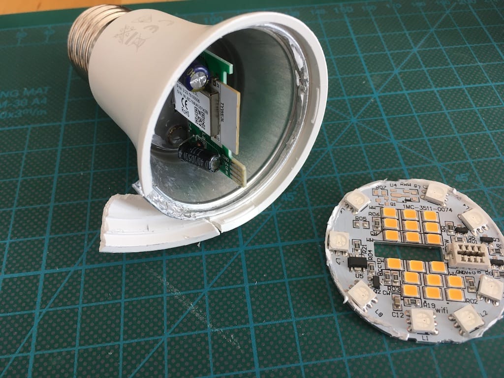
All components are tightly fixed by resin. The LED ring needs to be loosened - I actually cracked a part of the scaffolding but did not damage the chip. The custom PCBs lower part are covered as well, including its onboard pin outlets. After more than 20 minutes of scratch-cutting the resin, all pin outlets were visible, and the boards upper extension to the power socket as well.
Let’s check the details of the ESP chip. It’s a TYWE3L with 16 pins, from which the RX, TC, V+, Gnd and RST pin can be seen here:
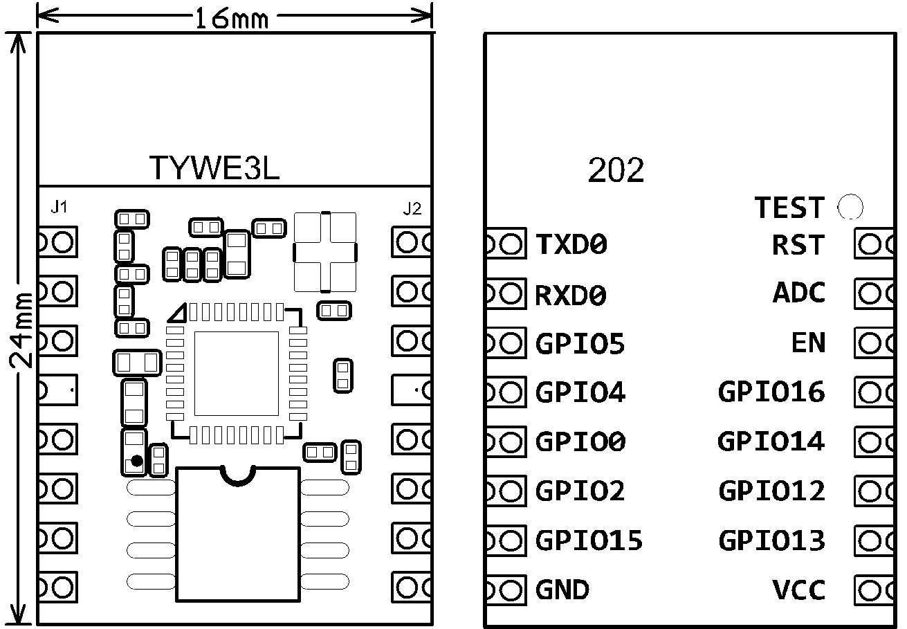
Source: https://tasmota.github.io/
These pins need to be connected to an FTL-USB adapter or similar device.
So far, so good. But getting wires attached to the pin outlet was an impossible challenge for me. The pin outlets are about 1.5mm big. Using either hook clamps with 0.09mm width, or alligator clamps, nothing could get a permanent connection to the pins. Although this article showed that it’s possible to solder wires directly to the board, I could not get enough space within the lightbulb shell.
After fiddling for 2 hours, I stopped and considered the options. I could carve the socket completely open but would essentially destroy the form factor of the lightbulb. Or I could fabricate a breakout board that sits on top of the chip. But considering the invested time in this project, and how easy it is to build a custom ESP board with addressable LED ring, I decided to forget the TYWE3L, but try to get the SM16716 working with a ESP8266.
And why not start with the LED ring that I just removed?
Bonus Try: Accessing the LED Ring with an ESP8266
I was intrigued by the LED ring: Can I control it with a custom ESPHome board? Thoroughly researching, I found out about RGBWW light. These consists of 7 pins: Vin, Ground, one pin for each of RGB, a pin for cold-white and one for warm-white. Suddenly, the CW and WW pin labels made sense!
With a new D1 Mini board, I connected all 7 pins and used this Home Assistant configuration:
light:
  - platform: rgbww
    name: "RGBWW"
    red: red_channel
    green: green_channel
    blue: blue_channel
    cold_white: cold_white_channel
    warm_white: warm_white_channel
    effects:
      - pulse:
      - strobe:
      - flicker:

output:
  - platform: esp8266_pwm
    id: red_channel
    pin: GPIO16
  - platform: esp8266_pwm
    id: green_channel
    pin: GPIO14
  - platform: esp8266_pwm
    id: blue_channel
    pin: GPIO12
  - platform: esp8266_pwm
    id: cold_white_channel
    pin: GPIO13
  - platform: esp8266_pwm
    id: warm_white_channel
    pin: GPIO15
Then came the moment of truth. Powering up the board showed that the components were recognized and available for controlling:
[16:58:50][D][light:035]: 'RGBWW' Setting:
[16:58:50][D][light:046]:   State: ON
[16:58:50][D][light:084]:   Transition length: 1.0s
[16:58:50][VV][api.service:122]: send_light_state_response: LightStateResponse {
[16:58:50]  key: 4101379364
[16:58:50]  state: YES
[16:58:50]  brightness: 0.501961
[16:58:50]  color_mode: COLOR_MODE_RGB_COLD_WARM_WHITE
[16:58:50]  color_brightness: 1
[16:58:50]  red: 1
[16:58:50]  green: 0.443137
[16:58:50]  blue: 0.254902
[16:58:50]  white: 1
[16:58:50]  color_temperature: 152.999
[16:58:50]  cold_white: 0.611765
[16:58:50]  warm_white: 0.439216
[16:58:50]  effect: 'None'
[16:58:50]}
But whatever value I send, I could not get a light. I measured the output if the power pin - works. I measured the PWW signals from the pins - they work too. But the board did not react. I connected just power and ground to see any LED going on. Nothing. Another 2 hours went by, and I could still not get it to work. This is enough.
Conclusion
This article showed three attempts a Hama WiFi LED Light. I tried three approaches, and they all failed.
First, flashing via Wi-Fi did not work because I apparently got a newer model of this Tuya device. Even when using a different second bulb, which was not connected once to my Wi-Fi, I could not get a connection between the Tuya Convert and the lightbulb. The pattern is obvious: The paring mode for the bulb lasts about 90 seconds. But immediately when I start the convert method, paring mode is disabled, I guess as a method of self-protection.
Second, I disassembled the lightbulb. The upper part of the showed the LED ring connected with a seven pin stub, and below it, the ESP8266 chip on a custom PCB. Half of the lightbulb was filled with synthetic resin. Even after cutting most off, the PCB stays fixed to the bulb socket. The boards interior is not accessible, I could not get a physical connection with clamp hooks.
Third, I tried to connect only the LED ring to a D1 mini board and configured it as RGBWW. Although I verified the workings of each pin, although the configuration was processed and Home Assistant showed a control panel, I could not get the lightbulb to show any light.
After spending about 6 in total, I stopped this endeavor and found a good working alternative: Custom LED rings based on the W2812B chipset, fully compatible with ESP Home and Home Assistant. Considering the price, the combination of a D1 mini and the LED ring is even more affordable. Let’s continue with this idea.