IOT Sensor Project: ESP8266 with DHT11 Sensor sends Data to MQTT
In my blog series so far, we covered how to setup the essential tools for transforming and capturing IOT data: MQTT, NodeRed, and InfluxDB. Now we will use these tools to actively collect data. The first sensor to be added is the temperature and humidity sensor DHT22. Its connected to an ESP8266 board. To flash and program it, we will use PlatformIO.
In this article you will learn a lot: How to use PlatformIO for programming ESP8266 chips, including board and library management, second how to implement reading temperature and humidity data from an DGHT11 sensor, and third how to send the sensor data via MQTT to your IOT stack.
The technical context for this article is Raspberry Pi OS 20.04, but the instructions should work for newer versions and other Linux distributions as well.
PlattformIO Setup
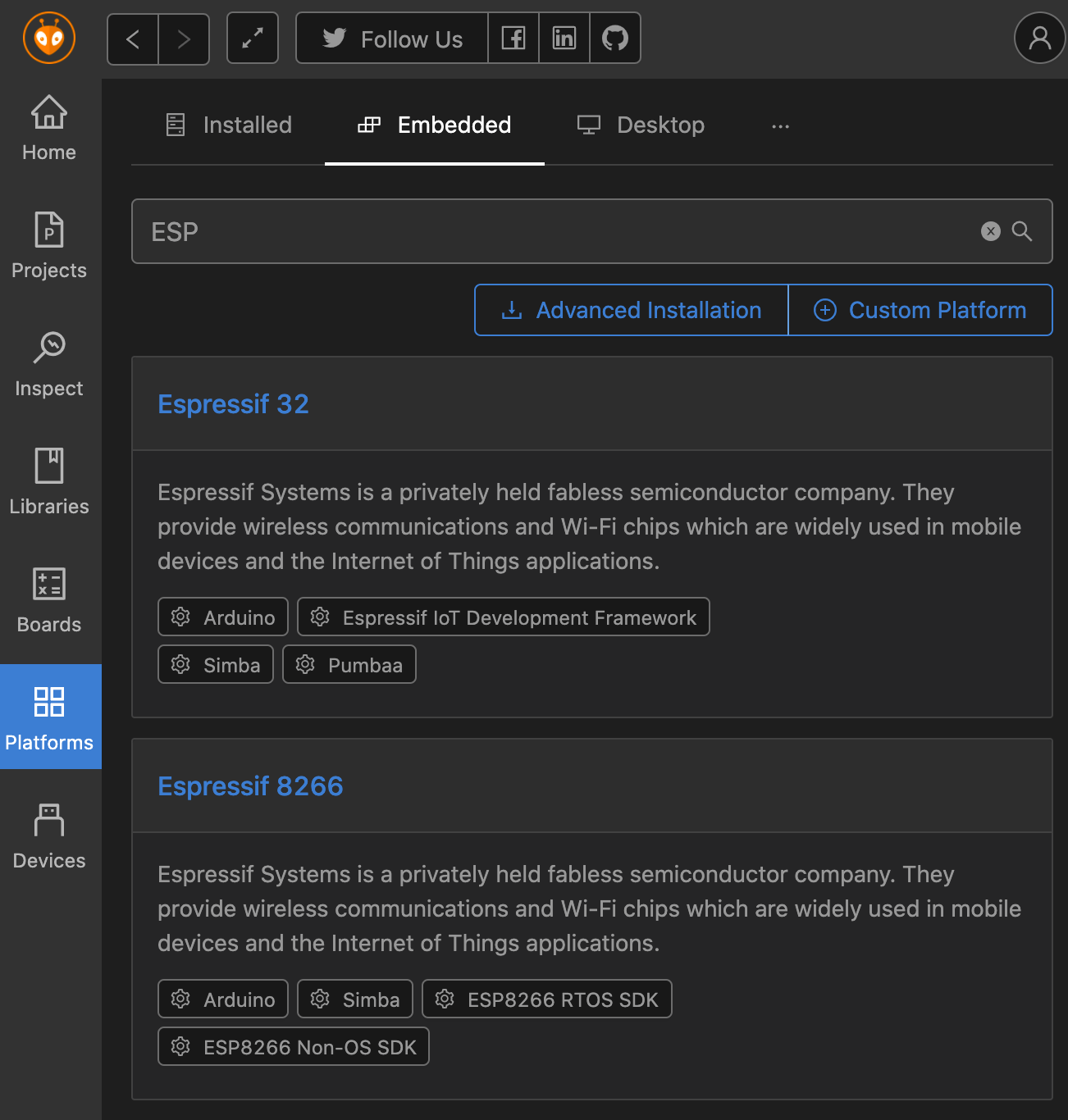
PlatformIO transform your Visual Studio Code IDE into a powerful environment for embedded programming. Its installed as a plugin and add a completely new screen to your IDE. With it, you can install platform and board support for a vast array of microcontrollers. And additionally, you can install and manage all libraries that you need for your project.
Here is a sample screenshot from the PlatformIO main page:
Once PlatformIO is installed, be sure to follow these additional steps to ensure a correctly working IDE:
- Copy & reload UDEV Rules that govern necessary permission rights to access hardware
$> curl -fsSL https://raw.githubusercontent.com/platformio/platformio-core/master/scripts/99-platformio-udev.rules | sudo tee /etc/udev/rules.d/99-platformio-udev.rules

$> udevadm control --reload-rules
- Add your user to specific system groups so that PlatformIO can access device files
sudo usermod -a -G dialout $USER
sudo usermod -a -G plugdev $USER
Adding ESP8266 Support to PlatformIO
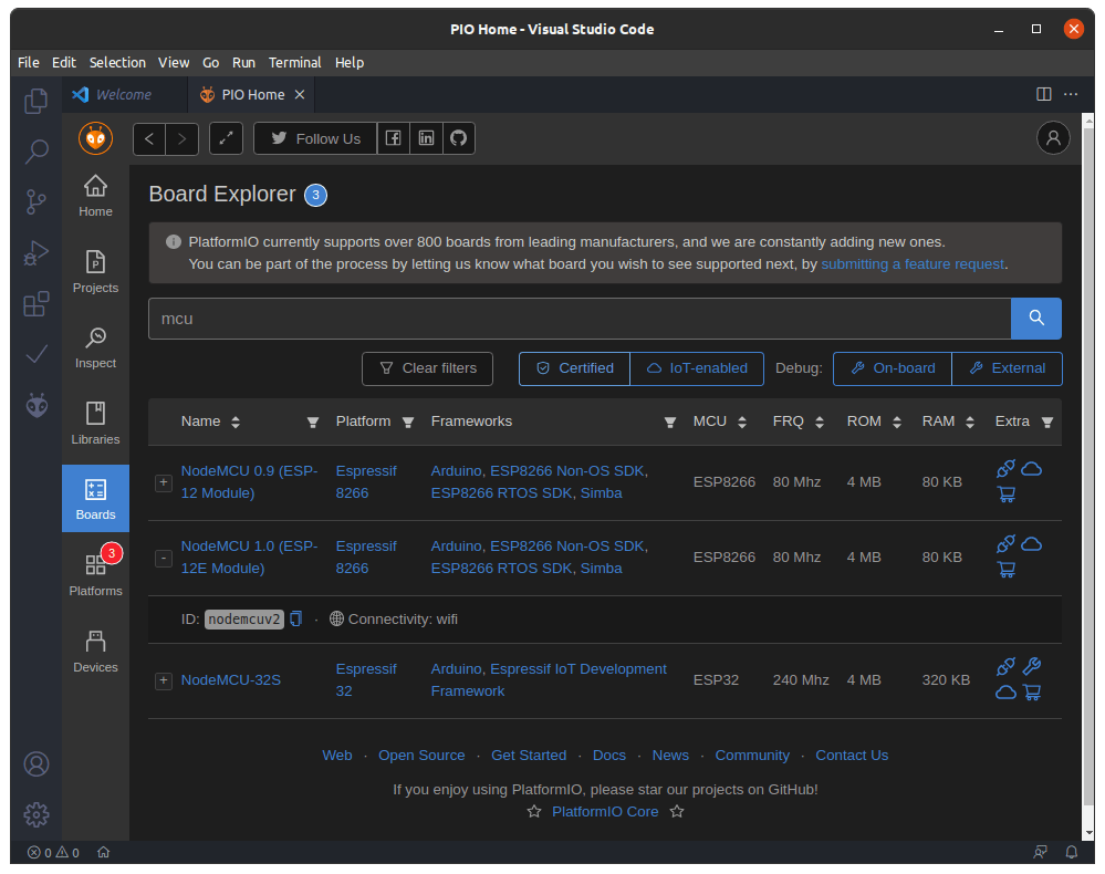
To add the board support, only two steps are required.
- Determine the correct version of your esp8266 board, and download the correct board version
- Create the project with the desired board
That’s it - now we can start programming.
Part 1: Test Program to Output Serial Data
Let’s start with a simple program that will just print a message to the serial monitor.
Copy and paste the following script:
#include <Arduino.h>

void setup()
 {
  Serial.begin(115200);
}

void loop() {
  digitalWrite(LED_BUILTIN, HIGH);
  delay(1000);
  digitalWrite(LED_BUILTIN, LOW);
  Serial.println("Hello World!");
}
Then, press the small arrow icon at the bottom of the IDE to start the upload process. A terminal should open and print the following messages:
> Executing task: platformio run --target upload <

Processing nodemcuv2 (platform: espressif8266; board: nodemcuv2; framework: arduino)
---------------------------------------------------------------------------------------------
Verbose mode can be enabled via `-v, --verbose` option
CONFIGURATION: https://docs.platformio.org/page/boards/espressif8266/nodemcuv2.html
PLATFORM: Espressif 8266 (2.6.2) > NodeMCU 1.0 (ESP-12E Module)
HARDWARE: ESP8266 80MHz, 80KB RAM, 4MB Flash
PACKAGES:
 - framework-arduinoespressif8266 3.20704.0 (2.7.4)
 - tool-esptool 1.413.0 (4.13)
 - tool-esptoolpy 1.20800.0 (2.8.0)
 - tool-mklittlefs 1.203.210628 (2.3)
 - tool-mkspiffs 1.200.0 (2.0)
 - toolchain-xtensa 2.40802.200502 (4.8.2)
LDF: Library Dependency Finder -> http://bit.ly/configure-pio-ldf
LDF Modes: Finder ~ chain, Compatibility ~ soft
Found 29 compatible libraries
Scanning dependencies...
No dependencies
Building in release mode
Compiling .pio/build/nodemcuv2/src/main.cpp.o
Linking .pio/build/nodemcuv2/firmware.elf
Retrieving maximum program size .pio/build/nodemcuv2/firmware.elf
Checking size .pio/build/nodemcuv2/firmware.elf
Advanced Memory Usage is available via "PlatformIO Home > Project Inspect"
RAM:   [===       ]  32.9% (used 26916 bytes from 81920 bytes)
Flash: [===       ]  25.1% (used 262200 bytes from 1044464 bytes)
...
Important: If you see any error at this point, such as a "could not open port" error, be sure to perform the steps mentioned above.
If all goes well, the installation will continue with the following messages:
Configuring upload protocol...
AVAILABLE: espota, esptool
CURRENT: upload_protocol = esptool
Looking for upload port...
Auto-detected: /dev/ttyUSB0
Uploading .pio/build/nodemcuv2/firmware.bin
esptool.py v2.8
Serial port /dev/ttyUSB0
Connecting....
Chip is ESP8266EX
Features: WiFi
Crystal is 26MHz
MAC: 8c:aa:b5:7c:2f:21
Uploading stub...
Running stub...
Stub running...
Configuring flash size...
Auto-detected Flash size: 4MB
Compressed 266352 bytes to 196349...

Writing at 0x00000000... (8 %)
Writing at 0x00004000... (16 %)
Writing at 0x00008000... (25 %)
Writing at 0x0000c000... (33 %)
Writing at 0x00010000... (41 %)
Writing at 0x00014000... (50 %)
Writing at 0x00018000... (58 %)
Writing at 0x0001c000... (66 %)
Writing at 0x00020000... (75 %)
Writing at 0x00024000... (83 %)
Writing at 0x00028000... (91 %)
Writing at 0x0002c000... (100 %)
Wrote 266352 bytes (196349 compressed) at 0x00000000 in 17.3 seconds (effective 122.9 kbit/s)...
Hash of data verified.
Excellent. When you connect PlatformIO to the serial monitor, you can see that the messages are printed.
Part 2: Connecting the DHT11 Sensor
The first step is wiring the DHT11 sensor to the ESP8266 board. You need to connect 5V, ground, and the data pin. Considering the data pin, see this excellent Pin layout guide In PlatformIO programs, you will reference the pins via their GPIO number.
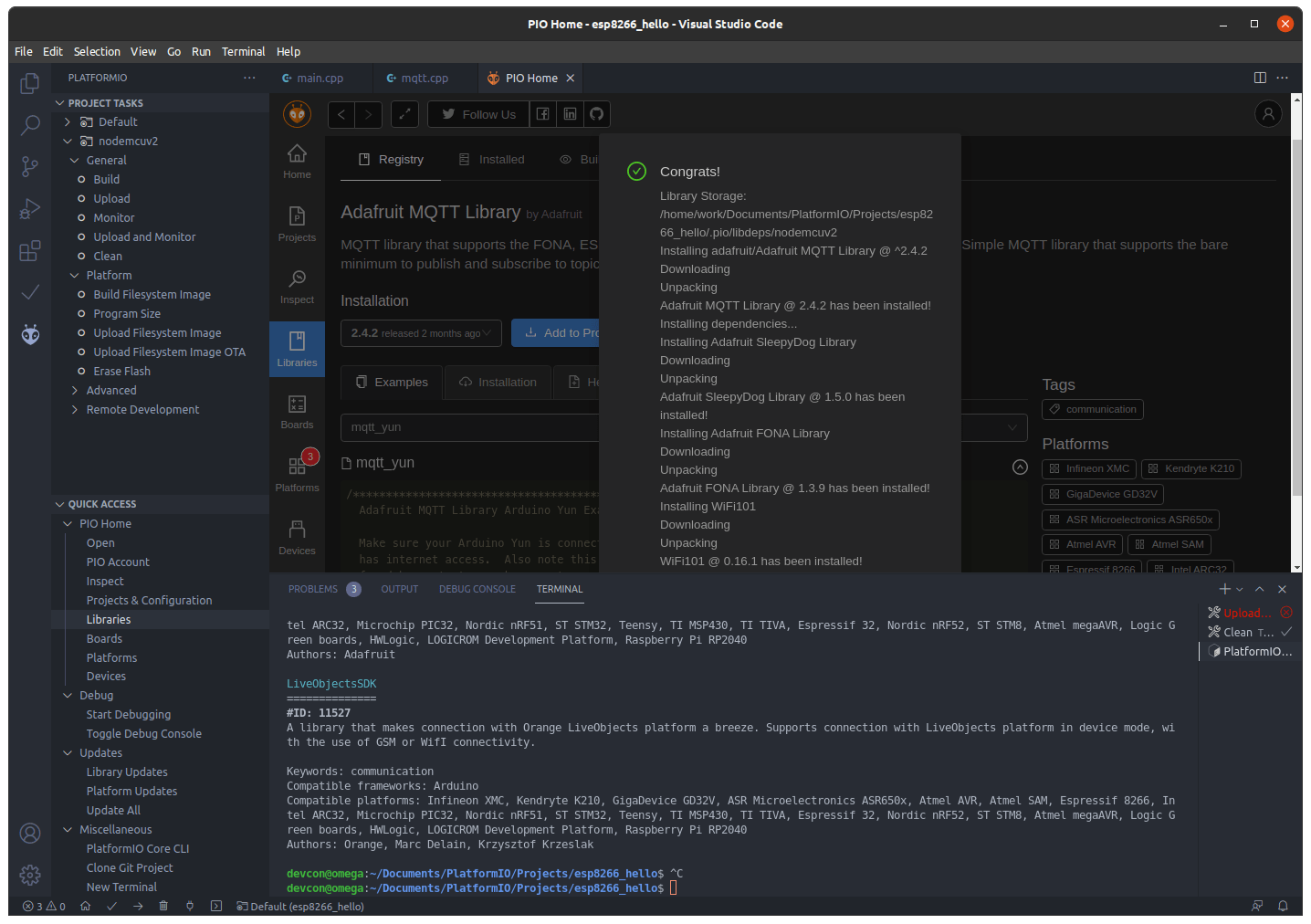
To read data from the DHT11, we will use the libraries AdafruitSensor, DHT and DHT_U. The AdafruitSensor library provides a general abstraction for several sensor types, on which the specific DHT library build. All libraries are installed with the PlatformIO library manager as shown in the following screenshot.
Following the official example, the following program reads from the sensors every 5 seconds, and prints the result via serial:
#include <Arduino.h>
#include <Adafruit_Sensor.h>
#include <DHT.h>
#include <DHT_U.h>

#define DHTPIN 5
#define DHTTYPE    DHT11

DHT_Unified dht(DHTPIN, DHTTYPE);

void MQTT_connect();

void setup() {
  Serial.begin(9600);
  dht.begin();
  delay(10);
}

void blink() {
  digitalWrite(LED_BUILTIN, HIGH);
  delay(300);
  digitalWrite(LED_BUILTIN, LOW);
}

void loop() {
  blink();

  sensors_event_t event;
  dht.temperature().getEvent(&event);

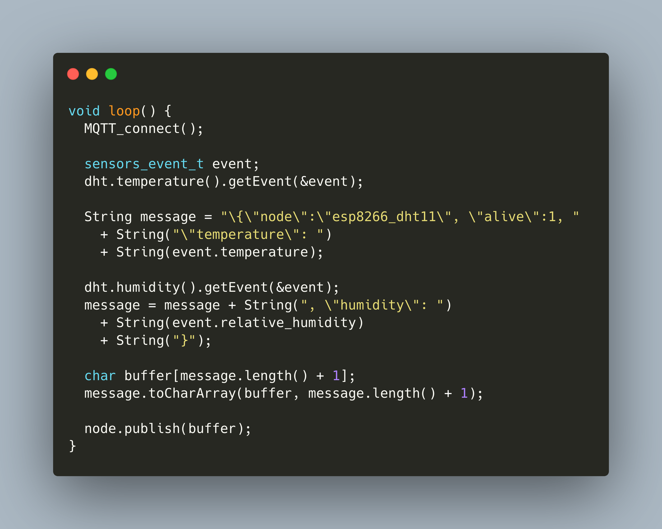
  String message = "\{\"node\":\"esp8266_dht11\", \"alive\":1, "
    + String("\"temperature\": ")
    + String(event.temperature);

  dht.humidity().getEvent(&event);
  message = message + String(", \"humidity\": ")
    + String(event.relative_humidity)
    + String("}");

  Serial.println(message);
  delay(50000);
}
Lets cover some aspects of this code:
- The DHT sensor object is created with
dht(DHTPIN, DHTTYPE)- be sure to use the correct data pin to which you connected, and to specify the correct sensor type - The sensor is started with
dht.begin(), and then readings are executed by callingdht.temperature()anddht.humidity() - Concreate measurements are stored in an
eventobject, which contains the concrete values.
Reading the temperature data works fine. Let’s continue with the setup of the wireless connection.
Part 3: Adding Wi-Fi Connection
For connecting to the wireless network, the library ESP8266WiFi will be used. This library provides objects and function to create a Wi-Fi connection and sending data. Continuing in the spirit of small working examples, here is the necessary code to make a Wi-Fi connection and print some connection details.
#include <Arduino.h>
#include <ESP8266WiFi.h>

#define WLAN_SSID       "WLAN_SSID"
#define WLAN_PASS       "WLAN_PASSWORD"

WiFiClient client;

void setup() {
  Serial.begin(9600);
  delay(10);

  Serial.print("Connecting to ");
  Serial.println(WLAN_SSID);

  WiFi.begin(WLAN_SSID, WLAN_PASS);
  while (WiFi.status() != WL_CONNECTED) {
    delay(500);
    Serial.print(".");
  }
  Serial.println();
}

void blink() {
  digitalWrite(LED_BUILTIN, HIGH);
  delay(300);
  digitalWrite(LED_BUILTIN, LOW);
}

void loop() {
  blink();

  Serial.println("WiFi connected");
  Serial.print("IP address: ");
  Serial.println(WiFi.localIP());

  delay(5000);
}
As you see, we create a client object. Inside the setup() method, we call WiFi.begin() in a continuous loop until the status switches to WL_CONNECTED. When this is fulfilled, the main loop repetitively prints the obtained IP address.
Here is some example output from this script.
Connecting to WIFI
........
WiFi connected
IP address:
192.168.42.112
Part 4: Connecting to MQTT and Sending Data
We are almost there. for adding MQTT to our program, we will again use Adafruit libraries: Adafruit_MQTT and Adafruit_MQTT_Client. There is a great official example that shows the core aspects about how to use the library. After several tries, here is the working version.
#include <Arduino.h>
#include <ESP8266WiFi.h>
#include "Adafruit_MQTT.h"
#include "Adafruit_MQTT_Client.h"

#define WLAN_SSID       "WLAN_SSID"
#define WLAN_PASS       "WLAN_PASSWORD"

#define SERVER      "192.168.42.1"
#define SERVERPORT  1883

WiFiClient client;
Adafruit_MQTT_Client mqtt(&client, SERVER, SERVERPORT, "", "");
Adafruit_MQTT_Publish node = Adafruit_MQTT_Publish(&mqtt, "/sensors");

void MQTT_connect();

void setup() {
  digitalWrite(LED_BUILTIN, LOW);
  Serial.begin(9600);
  delay(10);

  Serial.println("DHT11 MQTT Publisher");
  Serial.print("Connecting to ");
  Serial.println(WLAN_SSID);

  WiFi.begin(WLAN_SSID, WLAN_PASS);
  while (WiFi.status() != WL_CONNECTED) {
    delay(500);
    Serial.print(".");
  }
  Serial.println();

  Serial.println("WiFi connected");
  Serial.print("IP address: ");
  Serial.println(WiFi.localIP());

  MQTT_connect();
}

void loop() {
  String message = "\{\"node\":\"esp8266_dht11_test\", \"alive\":1}"

  Serial.println(message);

  char buffer[message.length() + 1];
  message.toCharArray(buffer, message.length() + 1);

  node.publish(buffer);

  delay(1000);
}

void MQTT_connect() {
  int8_t ret;

  Serial.print("Connecting to MQTT... ");

  uint8_t retries = 3;
  while ((ret = mqtt.connect()) != 0) {
       Serial.println(mqtt.connectErrorString(ret));
       Serial.println("Retrying MQTT connection in 5 seconds...");
       mqtt.disconnect();
       delay(5000);
       retries--;
       if (retries == 0) {
         while (1);
       }
  }
  Serial.println("MQTT Connected!");
}
There is quite some heavy lifting done for with this library. Let’s focus on the essentials
- The MQTT client is created with
Adafruit_MQTT_Client mqtt(&client, SERVER, SERVERPORT, "", ""), to which you pass the Wi-Fi client objects, then the IP and port of the MQTT server - An MQTT publisher is created with
Adafruit_MQTT_Publish(&mqtt, "/sensors"), which receives the MQTT client and a topic name to which it should publish - To prevent compilation errors, its important to define
void MQTT_connect();before thesetup()andloop()method, and then redefine it later - The connection is established by calling
mqtt.connect()and checking that its return code is not0; this is tried for three times with an additional waiting period in between - To publish a message, it needs to be converted to a
char[], then callnode.publish()
Storing and Visualizing DHT11 data
Finally, I put all the things together. The sensor starts and connects to the Wi-Fi. Then it uses the Wi-Fi connection to connect to the MQTT server. The DHT11 sensor data, temperature and humidity, are captured and manually parsed together to a JSON string. This string is converted to a C char array and send to the MQTT server. Afterwards, the sensor goes into deep sleep mode, waits for 30 minutes, and repeats these steps.
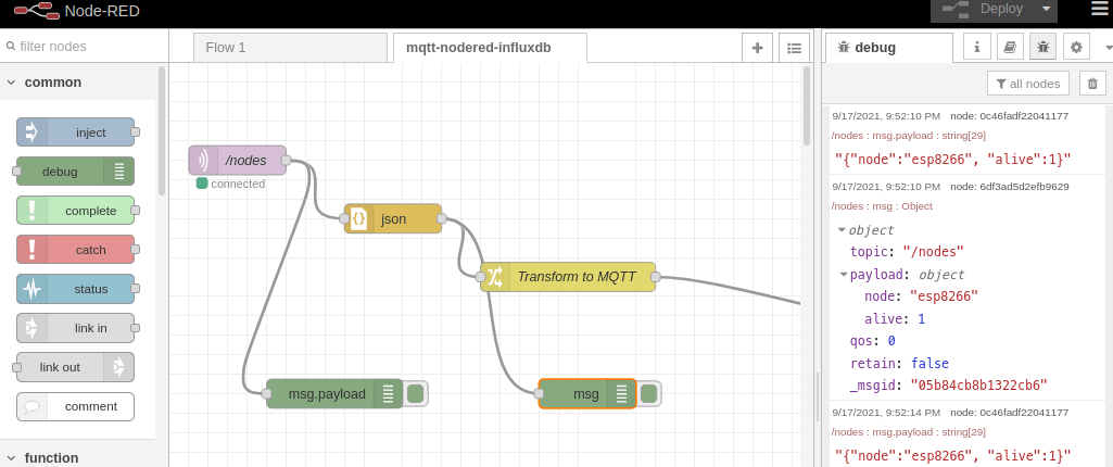
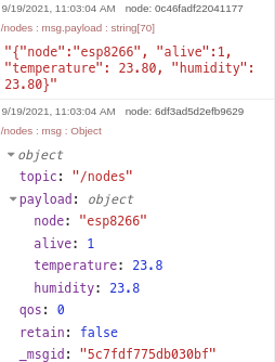
When the MQTT server receives the data, I use a NodeRed workflow to save it to InfluxDB. The workflow and an example payload are shown in the following picture:
Using the influx CLI, we can check that temperature data is correctly stored:
influx
Connected to http://localhost:8086 version 1.8.9
InfluxDB shell version: 1.8.9

> use sensors
Using database sensors

> show measurements
name: measurements
name
----
alive
cpu
cpu_temperatures
disk
environment
mem
system
> select * from environment
name: environment
time                humidity room        temperature
----                -------- ----        -----------
1632043840635145467 24.1     living_room 24.1
1632043856234155020 24       living_room 24
1632043871847026601 24       living_room 24
1632043887467691275 24       living_room 24
1632043903050309596 24       living_room 24
1632043918636092355 24       living_room 24
1632043934233190398 24       living_room 24
1632043949829200309 24       living_room 24
1632043965430243112 24       living_room 24
1632043981010088416 24       living_room 24
1632043996630429169 24       living_room 24
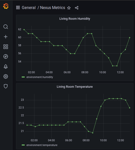
Finally, with a suitable Grafana dashboard, I can access the data stored in InfluxDB, and visualize it.
Complete Example Source Code
Here is the complete example.
#include <Arduino.h>
#include <ESP8266WiFi.h>
#include "Adafruit_MQTT.h"
#include "Adafruit_MQTT_Client.h"
#include <Adafruit_Sensor.h>
#include <DHT.h>
#include <DHT_U.h>


#define WLAN_SSID       "WLAN_SSID"
#define WLAN_PASS       "WLAN_PASSWORD"

#define SERVER      "192.168.42.200"
#define SERVERPORT  1883

#define DHTPIN 5
#define DHTTYPE    DHT11

#define DEEP_SLEEP_TIME 1800

WiFiClient client;
Adafruit_MQTT_Client mqtt(&client, SERVER, SERVERPORT, "", "");
Adafruit_MQTT_Publish node = Adafruit_MQTT_Publish(&mqtt, "/sensors");

DHT_Unified dht(DHTPIN, DHTTYPE);

void MQTT_connect();

void setup() {
  //pinMode(LED_BUILTIN, OUTPUT);
  digitalWrite(LED_BUILTIN, LOW);
  Serial.begin(9600);
  delay(10);

  dht.begin();
  delay(10);

  Serial.println("DHT11 MQTT Publisher");
  Serial.print("Connecting to ");
  Serial.println(WLAN_SSID);

  WiFi.begin(WLAN_SSID, WLAN_PASS);
  while (WiFi.status() != WL_CONNECTED) {
    delay(500);
    Serial.print(".");
  }
  Serial.println();

  Serial.println("WiFi connected");
  Serial.print("IP address: ");
  Serial.println(WiFi.localIP());
}

void blink() {
  digitalWrite(LED_BUILTIN, HIGH);
  delay(300);
  digitalWrite(LED_BUILTIN, LOW);
}

void loop() {
  MQTT_connect();
  blink();

  sensors_event_t event;
  dht.temperature().getEvent(&event);

  String message = "\{\"node\":\"esp8266_dht11\", \"alive\":1, "
    + String("\"temperature\": ")
    + String(event.temperature);

  dht.humidity().getEvent(&event);
  message = message + String(", \"humidity\": ")
    + String(event.relative_humidity)
    + String("}");

  Serial.println(message);

  char buffer[message.length() + 1];
  message.toCharArray(buffer, message.length() + 1);

  node.publish(buffer);

  if(! mqtt.ping()) {
    mqtt.disconnect();
  }

  ESP.deepSleep(DEEP_SLEEP_TIME * 1000000);
  yield();
}

void MQTT_connect() {
  int8_t ret;

  if (mqtt.connected()) {
    return;
  }

  Serial.print("Connecting to MQTT... ");

  uint8_t retries = 3;
  while ((ret = mqtt.connect()) != 0) {
       Serial.println(mqtt.connectErrorString(ret));
       Serial.println("Retrying MQTT connection in 5 seconds...");
       mqtt.disconnect();
       delay(5000);
       retries--;
       if (retries == 0) {
         while (1);
       }
  }
  Serial.println("MQTT Connected!");
}
Summary
In this article, you learned how to program an ESP826 board with a connected DHT11 sensor to read temperature/humidity values and send them to an MQTT border. Each individual step is explained in a dedicated section: a) Programming a simple "Hello World" program for the ESP8266, b) Reading temperature and sensordata, c) Connecting the ESP8266 to a Wi-Fi, and d) connect and publish to an MQTT server. Once temperature data is sent to MQTT, an NodeRed workflow is triggered to store the data in InfluxDB. Finally, the data is visualized with Grafana. Overall, I'm very satisfied with this project: My own inhouse temperature sensor works flawlessly ever since and I continuously collect the data.